The Foundation of Engineering Simulation: A Deep Dive into Meshing
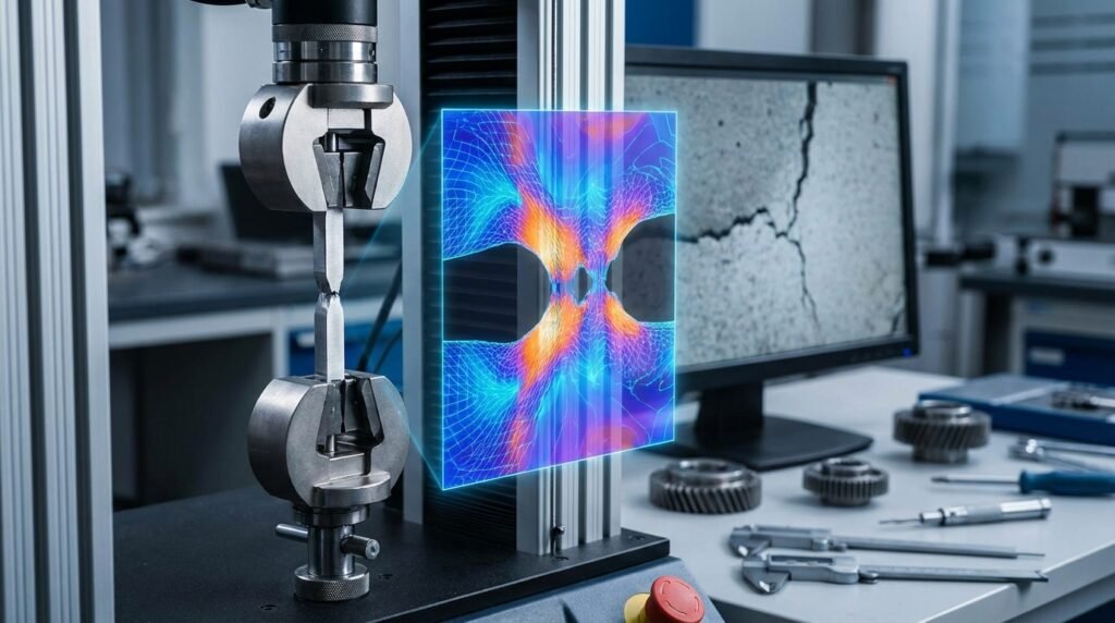
In the realm of engineering simulation, particularly within Finite Element Analysis (FEA) and Computational Fluid Dynamics (CFD), the process of meshing stands as a critical, often underestimated, precursor to accurate and reliable results. Meshing transforms a continuous physical domain—your engineering component, fluid volume, or assembly—into a discrete network of interconnected elements. This discretization allows complex partial differential equations governing physics to be approximated and solved numerically. For any engineer involved in structural integrity, fluid dynamics, heat transfer, or multiphysics simulations, a profound understanding of meshing principles is non-negotiable.
What is Meshing? The Digital Discretization
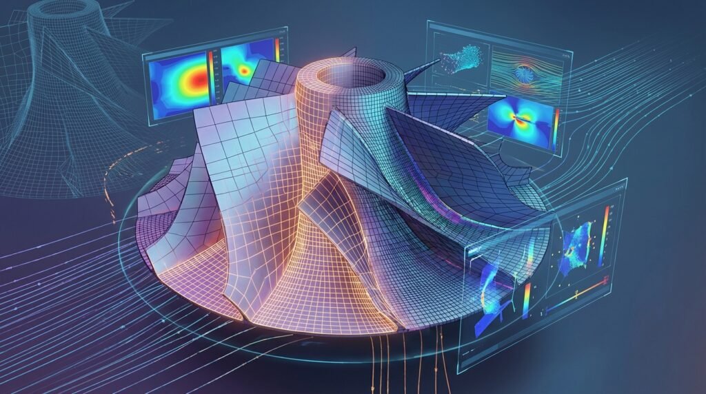
At its core, meshing is the art and science of dividing a CAD geometry into a finite number of smaller, simpler geometric entities called elements. These elements are connected at specific points known as nodes. The collection of all elements and nodes forms the mesh. This mesh then serves as the computational domain upon which the governing equations of a physical problem are applied and solved. The accuracy and computational cost of your simulation are inextricably linked to the quality and density of your mesh.
Why Meshing Matters: Impact on Accuracy, Performance, and Convergence
The mesh dictates how well the simulation software approximates the real-world behavior of a system. A poorly constructed mesh can lead to erroneous results, non-convergence, or excessively long computation times, rendering the entire simulation effort futile. Conversely, an intelligently designed mesh can significantly reduce simulation time while maintaining the required accuracy. Key impacts include:
- Accuracy: Finer meshes generally capture geometric details and solution gradients (e.g., stress concentrations, velocity boundary layers) more accurately.
- Convergence: A high-quality mesh, free from highly distorted elements, is crucial for numerical stability and ensuring the iterative solvers converge to a solution.
- Computational Cost: The number of elements directly influences the number of equations to be solved. A denser mesh means more computational memory and CPU time, potentially turning a quick analysis into an overnight run.
- Post-processing: A well-structured mesh can make post-processing of results clearer and more interpretable, aiding in design decisions and failure analysis.
Types of Meshes and Their Applications
Meshes are broadly categorized by the geometry of their elements and their overall structure. The choice of mesh type is often dictated by the geometry of the component, the type of analysis, and the required accuracy.
Element Geometries: The Building Blocks
Elements come in various shapes, each suited for different applications:
1D Elements (Beams, Trusses)
- Characteristics: Represent slender structures where one dimension is significantly larger than the other two. Nodes are at the ends.
- Applications: Structural frames, lattice structures, pipelines in oil & gas, rebar in concrete simulations. Tools like Abaqus and ANSYS Mechanical use beam elements extensively.
2D Elements (Shells, Membranes)
- Characteristics: Ideal for thin-walled structures where one dimension is much smaller than the other two. Examples include triangular (tri) and quadrilateral (quad) elements.
- Applications: Automotive body panels, aerospace fuselage and wing structures, sheet metal forming, pressure vessels, composite laminates. MSC Nastran and Abaqus are widely used for these applications.
3D Elements (Solids – Tetras, Hexas, Pyramids, Wedges)
- Characteristics: Represent bulky components where all three dimensions are comparable.
- Applications: Engine blocks, connecting rods, complex biological implants in biomechanics, fluid domains in CFD.
The most common 3D elements are:
- Tetrahedral (Tet) Elements: Four-noded (linear) or ten-noded (quadratic) elements. They are versatile for complex geometries but can be ‘stiffer’ than hexas and require more elements for the same accuracy in some cases.
- Hexahedral (Hex) Elements: Eight-noded (linear) or twenty-noded (quadratic) elements. Offer superior accuracy and efficiency for stress and flow predictions, especially in regions with high gradients, but are challenging to generate for intricate geometries.
- Pyramid and Wedge Elements: Often used as transition elements between hexahedral and tetrahedral regions, or when meshing features like fillets and sharp corners.
Mesh Structures: Organized or Adaptive
Beyond element shape, the overall arrangement of elements defines the mesh structure.
Structured Meshes (Hexahedral Dominance)
- Characteristics: Elements are arranged in a regular, grid-like pattern, often with hexahedral elements. Nodes can be indexed (i, j, k).
- Advantages: Excellent quality, high accuracy, faster convergence, efficient for solvers.
- Disadvantages: Extremely difficult, often impossible, to generate for complex geometries without significant manual effort or decomposition.
Unstructured Meshes (Tetrahedral Flexibility)
- Characteristics: Elements (typically tets or tris) are arranged without a regular pattern. Offers great flexibility.
- Advantages: Can be automatically generated for virtually any geometry, simplifying the pre-processing phase.
- Disadvantages: Can require more elements for similar accuracy to a structured mesh, potentially leading to higher computational costs.
Hybrid Meshes
- Characteristics: Combine structured and unstructured regions. For example, using hexas in critical regions and tets in less critical or geometrically complex areas.
- Applications: Very common in CFD, where structured boundary layers (prism/hexa elements) are used near walls to capture gradients accurately, while the bulk fluid domain is meshed with unstructured tets (e.g., in ANSYS Fluent or OpenFOAM).
Adaptive Meshing (h-refinement, p-refinement, r-refinement)
- Characteristics: The mesh is automatically refined or coarsened during the solution process based on error indicators.
- h-refinement: Adds more elements (e.g., splitting existing elements) in regions of high error.
- p-refinement: Increases the polynomial order of the shape functions used in existing elements, enhancing accuracy without increasing element count.
- r-refinement: Repositions existing nodes to regions of higher gradients, maintaining the number of elements.
- Advantages: Optimizes mesh density where it’s most needed, reducing overall element count while improving accuracy.
- Applications: Advanced FFS Level 3 assessments, crack propagation simulations, highly transient CFD problems.
Specific Applications: FEA vs. CFD Considerations
While meshing principles are universal, specific considerations apply to FEA and CFD:
- FEA (Stress, Structural Integrity): Focus on capturing stress concentrations, contact regions, and thin sections accurately. Quadratic elements often preferred for better stress interpolation.
- CFD (Fluid Flow, Heat Transfer): Critical to resolve boundary layers near walls with prism/inflation layers to accurately capture velocity and temperature gradients. Orthogonality and aspect ratio are paramount for numerical stability.
Practical Workflow for Effective Meshing
A systematic approach to meshing is vital for consistent, high-quality results.
Step 1: Geometry Preparation and Simplification
The adage “Garbage In, Garbage Out” applies strongly here. A clean, simplified CAD model is the cornerstone of good meshing.
Checklist: Geometry Cleanup
- Remove Redundant Features: Small holes, fillets, chamfers, or logos that do not significantly affect the primary physics and are below a certain tolerance.
- Repair Gaps and Overlaps: Ensure a watertight volume for 3D analysis, especially CFD.
- Defeature: Simplify complex surfaces, blend tangent edges, or remove small faces.
- Imprint/Partition: Create distinct regions for localized mesh control or to define contact surfaces and boundary conditions.
- Mid-surface Extraction: For thin-walled structures, extract mid-surfaces for 2D shell element meshing to save computational cost.
Tools: Dedicated CAD software (CATIA, SolidWorks, Inventor), CAE pre-processors (MSC Patran, Abaqus/CAE, ANSYS SpaceClaim/DesignModeler) offer robust geometry cleanup and simplification tools. Python scripting can automate repetitive cleanup tasks for large assemblies.
Step 2: Selecting the Right Mesh Type and Element Order
This decision impacts accuracy and computational cost significantly.
- Tetrahedral vs. Hexahedral: Tetras for geometric complexity, hexas for high accuracy, especially in load paths or flow regions. Consider hybrid options.
- Element Order (Linear vs. Quadratic): Quadratic elements (e.g., 10-node tets, 20-node hexes) capture bending and stress gradients more accurately with fewer elements but come with higher computational cost per element. Linear elements are faster for large models or initial studies where high precision isn’t paramount. For FFS Level 3 assessments involving crack growth or plasticity, quadratic elements are often mandated.
Step 3: Mesh Sizing and Density Control
This is where you balance accuracy with computational budget.
- Global vs. Local Sizing: Start with a coarse global mesh size and then apply local refinements to critical areas such as stress concentrations (fillets, holes), contact zones, material discontinuities, or regions of high solution gradients (e.g., boundary layers in CFD).
- Curvature-based Sizing: Automatically refines elements on curved surfaces to accurately capture geometry.
- Proximity-based Sizing: Refines elements between closely spaced surfaces, crucial for contact analysis or thin gaps.
- Boundary Layer Meshing (CFD): Essential for accurate CFD results. Create thin, highly aspect-ratio elements (prisms/hexas) perpendicular to walls to resolve the viscous sublayer and turbulent boundary layer. The first cell height (y+) is a critical parameter here.
Step 4: Meshing Techniques and Algorithms
Pre-processors offer various algorithms for mesh generation.
- Automatic Meshing: Most pre-processors (Abaqus/CAE, ANSYS Meshing, HyperMesh) have robust automatic tetrahedral meshing algorithms (e.g., advancing front, Delaunay triangulation).
- Manual/Semi-Automatic Meshing: Techniques like sweeping (extruding a 2D mesh into 3D) or mapped meshing (creating structured hex meshes on topologically simple regions) are used for higher quality or structured mesh generation. These are often preferred for critical components in aerospace or oil & gas structural integrity.
- Inflation Layers (CFD): A specialized technique to generate boundary layers using prism elements.
Step 5: Mesh Quality Metrics and Criteria
Assessing mesh quality is paramount. Most CAE tools provide diagnostics.
| Metric | Description | Impact on Simulation | Typical Acceptable Range |
|---|---|---|---|
| Aspect Ratio | Ratio of the longest edge to the shortest edge (or height). | High aspect ratio in critical regions can lead to inaccurate results or convergence issues, especially with 3D elements. Good for boundary layers. | < 5 for structural, < 20-100 for boundary layers in CFD. |
| Skewness | How close to equilateral an element is. Angle between adjacent element vectors. | High skewness indicates poor element shape, can cause inaccurate stress/flow predictions and convergence issues. | < 0.85 (tets), < 0.6 (quads/hexas) |
| Orthogonality | Angle between element faces and the normal vector passing through the centroid. | Crucial for CFD. Low orthogonality leads to numerical diffusion and inaccuracies. | > 0.1 for CFD |
| Jacobian Ratio | Measures element distortion relative to an ideal element. | Indicates if an element is inverted or severely distorted. Low values indicate bad quality. | > 0.1 (absolute) |
| Warpage (for Quads) | Deviation of an element’s face from a planar surface. | High warpage can lead to inaccurate bending behavior, especially for shell elements. | < 5-10 degrees (max) |
| Element Size Transition | How smoothly element size changes across regions. | Abrupt changes can introduce numerical errors. | Ratio < 1.5-2.0 between adjacent elements |
Tools: Abaqus/CAE, ANSYS Meshing, MSC Patran, OpenFOAM (checkMesh utility), and various proprietary pre-processors provide detailed mesh quality reports and visualization.
Advanced Meshing Strategies and Challenges
Meshing Complex Geometries
Modern engineering involves increasingly intricate designs. Meshing components with thin-walled structures, intricate fillets, small features, or highly curved surfaces requires advanced techniques, often involving a combination of global and local controls, virtual topology cleanups, and careful mid-surfacing.
Contact and Nonlinearities
For simulations involving contact, accurate mesh definition at potential contact interfaces is paramount. Elements should have compatible sizing, and often, finer meshes are required in these regions to prevent numerical noise or interpenetration. Specialized elements (e.g., gasket elements in Abaqus) also require specific meshing approaches.
Multiphysics and Fluid-Structure Interaction (FSI)
In FSI, a consistent mesh at the fluid-structure interface is critical for accurate data transfer between the fluid and structural solvers (e.g., ANSYS Fluent coupled with ANSYS Mechanical). Mesh motion and re-meshing strategies are often necessary for deforming interfaces.
Automation in Meshing
For repetitive tasks, parametric studies, or large-scale optimization, manual meshing is impractical. Scripting interfaces in commercial software (e.g., Abaqus Python API, ANSYS APDL, MSC Patran PCL) allow engineers to automate geometry cleanup, mesh generation, and quality checks. Open-source tools like OpenFOAM rely heavily on dictionary-based meshing utilities (e.g., blockMesh, snappyHexMesh) that can be automated with shell scripts or Python.
For complex automation tasks or custom scripting, explore the downloadable Python/MATLAB scripts and tutorials available on EngineeringDownloads.com to streamline your meshing workflows.
Verification & Sanity Checks: Ensuring Mesh Integrity
Never trust a mesh implicitly. Rigorous verification is essential.
Pre-Analysis Checks
- Visual Inspection: Zoom into critical areas. Look for jagged edges, highly distorted elements, or sudden transitions.
- Free Edges/Faces: Identify unintended gaps or holes that would indicate an unclosed volume or surface.
- Overlapping Elements: Ensure no elements are intersecting or defined in the same space, which can lead to severe numerical errors.
- Element Normals: Verify consistent element normal orientations, especially for shell elements, to prevent issues with pressure loads or contact.
Mesh Sensitivity Studies (Convergence)
This is arguably the most critical step to validate your mesh. It involves running the simulation with progressively finer meshes and observing the change in key results.
Methodology:
- Start with a relatively coarse mesh and run the simulation. Record a key output parameter (e.g., maximum stress, peak displacement, pressure drop, lift coefficient).
- Refine the mesh (e.g., by 20-30% global element count or by locally refining critical regions) and re-run.
- Plot the key output parameter against the number of elements or element size.
- Continue refining until the change in the key output parameter falls below a predefined tolerance (e.g., less than 5% change, or less than 1% for high-fidelity studies). This indicates that the solution has converged with respect to the mesh.
Illustrative Example: In a structural analysis of a bolted joint, you might refine the mesh around the bolt hole until the maximum Von Mises stress in that region stabilizes within a 2% band across successive refinements. For a CFD analysis of a pipe flow, you would refine the mesh (especially boundary layers) until the pressure drop across the pipe or the average velocity at an outlet converges.
Post-Processing and Error Indicators
Many solvers provide error indicators (e.g., strain energy density error in FEA, truncation error in CFD) that can guide further mesh refinement, particularly in adaptive meshing schemes.
The Art of Mesh Refinement: Localized vs. Global
Always prioritize localized refinement over global refinement. Unnecessarily fine meshes in non-critical regions waste computational resources. Focus your refinement efforts where gradients are high, and accuracy is paramount. This often involves careful use of mesh controls (sizing functions, bias factors) in your pre-processor.
Best Practices for Robust Meshing
General Guidelines
- Start Simple: Begin with a coarser mesh to establish initial simulation behavior before refining.
- Targeted Refinement: Only refine where necessary—areas of high stress, high-velocity gradients, contact zones, etc.
- Avoid Distortion: Prioritize elements with good aspect ratios, low skewness, and high orthogonality.
- Gradual Transitions: Ensure element size changes smoothly to avoid numerical noise.
- Documentation: Record your meshing strategy, parameters, and mesh sensitivity study results for reproducibility and future reference.
Industry-Specific Tips
- Oil & Gas (FFS Level 3): For Fitness-for-Service Level 3 assessments, extremely high mesh quality is required, especially around crack tips or flaws for fracture mechanics analysis. Often requires 20-node brick elements or specialized crack-tip elements.
- Aerospace: Critical for weight optimization and structural integrity. Often demands highly structured meshes for wings and fuselages, and meticulous attention to detail in areas like engine mounts or landing gear attachments.
- Biomechanics: Complex, often organic geometries (bones, tissues) necessitate robust tetrahedral meshing, with careful refinement around implants or interfaces to accurately model biological responses.
- CAD-CAE Workflows: Establish clear guidelines for CAD model cleanup and simplification early in the design phase to facilitate efficient meshing downstream.
Conclusion: Mastering the Mesh
Meshing is more than just clicking a button; it’s an intricate engineering discipline that directly impacts the fidelity and efficiency of your simulations. By understanding element types, mastering meshing techniques, rigorously checking quality, and performing diligent mesh sensitivity studies, engineers can unlock the full potential of FEA and CFD. A well-constructed mesh is not merely a collection of elements; it is the robust foundation upon which accurate engineering insights are built, leading to better designs, safer products, and more efficient processes across all engineering domains.