


Introduction to Fracture Mechanics in FFS and ASME Design (with Abaqus, Ansys & COMSOL)
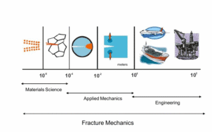
Did you know a tiny crack in a large pressure vessel or pipeline can lead to sudden failure, even if the overall stress is well below the material’s yield strength? This scary scenario has real examples – like ships splitting in two without warning (as in Figure 1 above) – and it’s exactly what Fracture Mechanics helps us understand and avoid. Fracture mechanics is the branch of engineering that focuses on cracks: how they start, grow, and cause failures in materials. Unlike traditional design which assumes perfect, flaw-free materials, fracture mechanics recognizes that real materials contain flaws (tiny cracks, weld defects, etc.) and provides tools to manage those cracks so they don’t turn into disasters. In this friendly introduction, we’ll break down the key concepts of fracture mechanics, why it’s so important for safety, and how it’s applied in Fitness-For-Service (FFS) assessments and ASME code-based design. We’ll also see how modern simulation tools – Abaqus, Ansys, and COMSOL – let us predict crack behavior with impressive accuracy. By the end, you’ll understand how engineers use fracture mechanics to keep oil & gas facilities, nuclear plants, and other structures safe while saving money by avoiding unnecessary repairs. Let’s dive in!
What is Fracture Mechanics and Why Does It Matter?
Fracture Mechanics is the study of how and why materials break (fracture) under stress, especially in the presence of cracks. In simple terms, it asks: “If there is a crack in a structure, will it grow and cause failure? And at what load or conditions?” Instead of treating materials as perfectly strong and uncracked, fracture mechanics assumes cracks exist (or could exist) and investigates how those cracks affect the material’s strength and durability. It provides mathematical relationships between three key factors: the stress on the structure, the size of a crack (or flaw), and the material’s fracture toughness (its resistance to crack growth). Using these relationships, engineers can predict whether a given crack will stay stable or suddenly propagate and cause a fracture.
Why is this important? Because history and tests have shown that even a small crack can drastically amplify stress locally. The stress at a sharp crack tip can be much higher than the average stress – often leading to failure at loads that would be harmless for an uncracked part. In fact, classical strength-of-materials design (the kind you learn in school, using yield strength and safety factors) sometimes fails to predict these crack-caused failures. Fracture mechanics fills that gap – it’s a vital tool for designing against unexpected failures. For example, engineers learned this the hard way during WWII when Liberty ships and tankers like the Schenectady cracked in half in cold waters without any obvious overload. Those fractures occurred at stresses far below the normal yield stress because of brittle material behavior and crack presence. These incidents spurred the development of modern fracture mechanics in the 1940s–50s, as pioneers like A.A. Griffith (who first modeled cracks in 1920) and G.R. Irwin (who introduced practical fracture toughness concepts in the 1950s) laid the foundation.
In summary, fracture mechanics matters because it allows engineers to predict failures that traditional analysis would miss. It acknowledges that all structures have flaws, and provides methods to ensure those flaws don’t grow into catastrophic breaks. This is crucial in safety-critical industries like oil & gas, nuclear, aerospace, and civil infrastructure, where a sudden fracture could be disastrous. By applying fracture mechanics, we can design more resilient structures, determine safe operating limits for damaged equipment, and make informed decisions about repairs – ensuring safety without prematurely scrapping components that can still be used with careful assessment.
Brittle vs. Ductile Fracture: How Materials Break
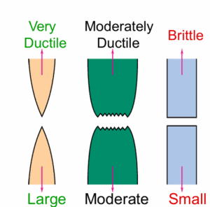
Not all fractures are the same. Materials generally exhibit two extreme types of fracture behavior:
- Brittle Fracture: A sudden, catastrophic break with little to no plastic deformation (no significant stretching or bending as warning). Brittle fractures often occur at high speeds and along a relatively flat path. The classic image of brittle fracture is something like glass shattering or the hull of a ship cracking cleanly (as in Figure 1). In metals, brittle fracture usually happens at lower temperatures or in very high-strength, low-toughness materials. It’s dangerous because it gives no warning – the material doesn’t visibly yield or sag; it just snaps. The fracture surface in a brittle failure is usually shiny or crystalline and may show a chevron or fan pattern pointing to the crack origin.
- Ductile Fracture: A slow, progressive failure with significant plastic deformation before complete breakage. Ductile materials (like mild steel at room temperature) tend to bend, stretch, and form a neck (localized thinning) as they fail. This absorbs a lot of energy. When ductile fracture finally occurs, it often leaves a rough, fibrous-looking surface and happens after the material has yielded and deformed visibly. Ductile failures are preferred (from a safety standpoint) because the structure usually gives warning (through deformation, like a bulge or a bend) before complete rupture. Think of a steel rod that bends and forms a crack gradually, versus a piece of cast iron that might snap in two suddenly – the steel’s failure is ductile, the iron’s is brittle.
Several factors determine whether a material behaves in a brittle or ductile manner: material toughness, temperature, strain rate, and the presence of flaws. Even a normally ductile material can behave in a brittle way under the wrong conditions – for example, steel that’s tough at room temperature can become brittle in extreme cold (this was a factor in the Liberty ship failures). Impurities and metallurgical structure also play a role: certain alloying elements or heat treatments can raise strength but lower toughness (making fracture more brittle). That’s why design codes (like ASME) often require a minimum Charpy impact toughness or set a safe minimum operating temperature – to ensure we have a cushion against brittle fracture.
Bottom line: Brittle fracture is fast and without warning, needing much caution, whereas ductile fracture is slower and more forgiving. A good design aims to have materials behave ductilely under expected loads – and uses fracture mechanics to check that even if a crack is present, it won’t cause a sudden brittle break. If there’s a risk of brittle behavior (due to low temperature or a very high-strength alloy), fracture mechanics analysis becomes even more critical to ensure safety.
Fundamentals of Fracture Mechanics: Cracks, Stress Intensity, and Toughness
Let’s break down some key concepts and terms in fracture mechanics:
- Crack Tip Stress Concentration: A crack in a material creates a very high stress at its tip. In fact, for a sharp crack in an elastic material, theory shows stress tends toward infinity right at the crack tip! While in reality materials will yield or blunt the crack to prevent infinite stress, the idea is that even a small crack can significantly amplify stress locally. This is why a part can fail at an average stress much lower than its normal strength – the crack-tip area experiences a much higher stress than the nominal load. Engineers needed a way to quantify “how much” a given crack and load will amplify stress, which leads to the concept of Stress Intensity.
- Stress Intensity Factor (K): This is a fundamental parameter in Linear Elastic Fracture Mechanics (LEFM). Think of K as a measure of the intensity of the stress field near a crack tip under a given load. It depends on the load, crack size, and geometry (including crack shape and component shape). For example, a longer crack or higher load gives a higher K. There are three modes of crack loading (Mode I – opening, Mode II – sliding, Mode III – tearing), each with its own stress intensity factor (K_I, K_II, K_III), but Mode I (opening mode) is the most common and usually the most critical. The critical idea is that if the stress intensity K at the crack tip reaches a certain threshold, the crack will propagate. That threshold is a material property called Fracture Toughness. For brittle (linear elastic) conditions, the fracture toughness is denoted K_IC (Critical K for mode I, in plane strain). If K < K_IC, the crack will not grow (stable); if K reaches K_IC, the crack can rapidly grow and cause fracture. The units of K are MPa·√m (or in Imperial units, ksi·√in). Engineers can obtain K for simple cases from formulas, or use Finite Element Analysis (FEA) for complex structures. For instance, if we have a crack of length a in a plate under stress σ, the Mode I stress intensity is roughly K = Y * σ * √(πa) (where Y is a dimensionless geometry factor) – showing that longer cracks and higher stress raise K.
- Fracture Toughness (K_IC): This is a property that measures a material’s resistance to crack propagation in a brittle (linear elastic) regime. Materials with high K_IC (like many aerospace alloys, or tempered steel) can tolerate higher stress or larger cracks before fracturing, whereas low K_IC materials (like glass, ceramics, or brittle cast iron) fracture at relatively low stress or small crack sizes. Toughness can depend on temperature and thickness (thicker specimens often have lower plane-strain toughness). For design, codes often provide minimum required K_IC or related measures, especially for fracture-critical applications. It’s important to note that fracture toughness is not the same as tensile toughness or strength – for example, high-strength steel may have lower fracture toughness (making it more brittle).
- Griffith’s Energy Criterion: The earliest fracture theory (by A.A. Griffith) considered the energy balance for crack growth in brittle materials. In simple terms, a crack will grow if the energy released (from relieving stress as the crack extends) exceeds the energy required to create new crack surfaces. This gave a criterion for brittle fracture and explained why observed strengths are far lower than theoretical (because creating new surfaces – breaking atomic bonds – consumes energy). Griffith’s work was specific to ideal brittle materials (like glass), but it laid the groundwork. In modern terms, the Strain Energy Release Rate G is used (with G_C as the critical value for fracture). For linear elastic materials, G relates to K (they’re two sides of the same coin: high K means high energy release rate).
- Linear Elastic Fracture Mechanics (LEFM) vs. Elastic-Plastic Fracture Mechanics (EPFM): LEFM assumes the material around the crack tip behaves elastically up to fracture. This is valid for brittle materials or when plasticity is very limited (e.g. small-scale yielding at the tip). In LEFM, K and G are the main parameters, and fracture occurs when K = K_IC (or G = G_C). However, many engineering materials (like structural steels, aluminum alloys) undergo significant plastic deformation at the crack tip before fracturing. That’s where EPFM comes in – it accounts for plasticity. EPFM uses parameters like the J-Integral and CTOD:
- J-Integral: Think of J as an extension of the energy release concept to elastic-plastic conditions. J represents the energy per unit crack growth (in a nonlinear material) and is path-independent under certain conditions. At the initiation of crack growth in a ductile material, J reaches a critical value J_IC (analogous to K_IC for brittle fracture). The J-integral is powerful because it can account for plastic work around the crack tip. FEA software often computes J for you via contour integrals around the crack tip.
- CTOD (Crack Tip Opening Displacement): This is another measure used mainly in EPFM and in standards like BS 7910. It literally measures how much the crack faces have opened at the tip at the moment of fracture. A critical CTOD indicates fracture. It’s conceptually easy – a tougher material will allow a larger CTOD before fracturing. CTOD is often used in weld defect assessments and ties closely to toughness tests (some fracture toughness tests measure CTOD at failure).
In practice, LEFM is used when the plastic zone at the crack tip is small compared to crack length and component size (so things are mostly elastic outside a tiny region). EPFM is used when there’s substantial yielding (common in ductile metals at service loads). Engineers will choose the appropriate approach based on material and crack size. For example, a thick pressure vessel made of ductile steel at operating temperature might still be treated with LEFM if a crack is small (tiny plastic zone), but a large crack or thinner section might need EPFM analysis.
- Failure Assessment Diagram (FAD): This is an important concept in fitness-for-service assessments (more on that soon). An FAD is essentially a graph that combines fracture and plastic collapse in one assessment. Without getting into the equations here, it plots a fracture ratio (like K/K_IC) on one axis and a load ratio (like applied stress / yield stress) on the other. The diagram has an envelope (a curve) within which the flaw is acceptable. If the assessment point (based on your crack size and load) lies inside the safe zone, the crack is tolerable; if it’s outside, the component is not fit for service. The FAD approach is popular in standards (API 579, BS 7910) because it gracefully handles the transition from brittle fracture to ductile yielding. It basically checks: are we near fracture-dominated failure or yield-dominated failure or neither? We might revisit FAD when discussing FFS, but it’s good to know it exists as a tool combining the above concepts.
- Fatigue Crack Growth: Many cracks grow gradually under cyclic loading (fatigue) rather than appearing at full size all at once. Fracture mechanics also encompasses fatigue crack growth laws, the most famous being Paris’ Law. Paris’ Law says that crack growth per cycle (da/dN) relates to the range of stress intensity (ΔK) in a power-law fashion: da/dN = C * (ΔK)^m, where C and m are material constants. Using such laws, engineers can predict how a crack will extend over time (e.g., how many cycles until a crack grows from 5 mm to 50 mm). This is crucial for scheduling inspections and maintenance – especially in aircraft, turbines, or anywhere cyclic loads occur. Fatigue crack growth analysis is a whole topic of its own (see our other guides), but it’s worth mentioning here because finding a crack is often just the start – we then use fracture mechanics to predict its future growth and decide when we must intervene.
These fundamentals – K, toughness (K_IC/J_IC), LEFM vs EPFM, FAD, and fatigue crack growth – form the toolkit of fracture mechanics. In real assessments, you might use one or several of these. For instance, you might calculate a stress intensity factor for a detected crack, compare it to the toughness (K_IC) to check immediate safety, and also use Paris’ Law to estimate how long the crack can grow before reaching critical size. Modern simulation tools can even calculate K or J for complex 3D cracks, which helps a lot in assessment accuracy.
Applying Fracture Mechanics in Fitness-For-Service (FFS) Assessments
Finding a flaw in an in-service component (like a crack in a pipeline weld or a reactor vessel nozzle) raises the big question: can we keep using this equipment safely, or must we repair/retire it? This is where Fitness-For-Service (FFS) assessments come in. FFS is a structured engineering approach to evaluate whether equipment with flaws or damage is fit to continue operation, and for how long. In other words, instead of panic and immediately replacing a vessel that has a crack, we perform an FFS analysis using fracture mechanics to decide if the crack is still within safe limits.
Industry Standards: The most widely used FFS standards are API 579-1/ASME FFS-1 (jointly published by the American Petroleum Institute and ASME) and the British Standard BS 7910. Both provide procedures to assess various types of flaws (cracks, corrosion, dents, etc.). For crack-like flaws, these standards heavily rely on fracture mechanics. In fact, they were developed so that aging equipment with flaws can be safely evaluated using state-of-the-art fracture methods, rather than automatically condemning the equipment. The goal is safety and cost-effectiveness: ensure protection of personnel and environment while avoiding unnecessary downtime if the flaw is tolerable.
FFS Assessment Levels: Typically, FFS codes have multiple levels of assessment: – Level 1: A conservative, quick screening. Often uses simple charts or formulae and lots of safety margin. For cracks, a Level 1 might simply say “if the crack length is less than X, it’s ok for now; if more, go to Level 2 or repair.” It usually doesn’t require extensive calculation. – Level 2: A more detailed assessment with refined calculations. Might involve computing a stress intensity factor using handbook solutions and comparing to toughness, or using an analytical FAD approach with code-specified reference curves. Level 2 allows more inputs (like actual material toughness data) to reduce conservatism. – Level 3: The most detailed (and least conservative) assessment – often involving numerical analysis (finite element analysis) and/or a case-specific stress analysis. Level 3 is where full fracture mechanics comes into play. You might perform an elastic-plastic FEA to get J-integral values, or a customized FAD using actual stress-strain curves, etc. Basically, Level 3 leverages computational methods to get as close to the real behavior as possible. It’s used when Level 2 results are borderline or overly conservative, or the geometry/loading is too complex for handbook solutions.
Using fracture mechanics in FFS, we can do things like: – Calculate the safety factor against fracture for a known crack size under operating loads. For example, if we find a crack 10 mm long in a pressure vessel, we compute K for operating pressure and compare it to K_IC. If K is well below K_IC (or the FAD point is within safe zone), the vessel can continue to run for now. If it’s too close or exceeds limits, we need repair or other actions. – Determine the critical crack size – how big can the crack grow before it causes failure? Perhaps a crack can grow to 50 mm before becoming critical; if our inspection found it at 10 mm, we have some margin. – Estimate remaining life or inspection interval by fatigue crack growth. For instance, predict that it will take X more years or Y more cycles for the crack to reach critical size. This helps plan the next inspection or a scheduled outage for repair before failure. – Evaluate changes in operating conditions: maybe we reduce the operating pressure or temperature to extend the life. For example, running at a lower pressure lowers the stress intensity, possibly keeping the crack stable. – Assess brittle fracture risk: FFS often checks if operating temperature is above the material’s ductile-to-brittle transition. If not, additional analysis is done to ensure no brittle fracture (Part 3 of API 579 is specifically about brittle fracture assessment). This ties into fracture mechanics by requiring adequate toughness at the minimum operating temperature.
A core tool in FFS crack assessment is the Failure Assessment Diagram (FAD) mentioned earlier. Both API 579 and BS 7910 use the FAD approach for crack-like flaws. Here’s how it works in practice: you calculate two ratios – K_r (the ratio of applied stress intensity K_I to K_IC) and L_r (the ratio of applied load or stress to the plastic collapse load, essentially how close you are to yielding). These (L_r, K_r) define a point on the diagram. The codes provide a curve (the FAD curve) which represents the boundary of failure. If your point is below the curve, the flaw is acceptable; if it’s on or above the curve, it’s not acceptable. This method inherently considers both fracture and yielding. For example, at L_r = 1 (general yield), the curve drops – indicating that if you’re at yield, even a small crack (K_r above 0) might be an issue. Conversely, at K_r = 1 (K equals toughness), the curve usually allows L_r somewhat less than 1, meaning even before full yield you’d fail by fracture. Using the FAD, FFS Level 2 or 3 assessments can give you a clear picture of safety. Both API 579 and BS 7910 have slight differences in the curves and details, but the philosophy is the same.
Advanced FFS (Level 3): This often means doing a finite element simulation to get the data needed for the FFS evaluation. For instance, if the component is very thick or the crack is an odd shape, simple handbook K formulas might be inaccurate. So an engineer might build an FEA model (using Abaqus, Ansys, etc.) of the component with the crack, apply the loads, and extract J-integral or K values. Those then feed into the FFS assessment (e.g., computing K_r). Advanced FFS might also consider ductile tearing: a crack might grow a little in a stable manner before final failure. There are procedures to account for that, often using J-resistance (J-R) curves from material testing. This is quite specialized, but just know that Level 3 can handle cases where the crack will extend slightly (stable crack growth) by incrementally checking the FAD as the crack grows.
Another aspect of advanced FFS is probabilistic assessment or sensitivity analysis – figuring out how variability in crack size or toughness affects the outcome. But that’s beyond an introduction; typically FFS is done in a deterministic but conservative way.
In summary, fracture mechanics is the backbone of crack assessment in FFS: – It provides the criteria to decide safe/unsafe flaw. – It helps optimize decisions: e.g., continue operation with monitoring, reduce load, repair now vs. later. – It is codified in standards to ensure engineers follow proven methods.
By using FFS with fracture mechanics, industries (oil & gas, chemical, power generation, etc.) have saved millions of dollars and avoided unplanned shutdowns – while still maintaining safety. Instead of assuming any crack is fatal, we can make data-driven decisions. For example, a refinery might find a crack in a pressure vessel during inspection right before a scheduled startup. Instead of delaying production for an immediate repair, an FFS Level 3 assessment might show the crack can safely last until the next planned turnaround. Or conversely, FFS might red-flag a flaw that looked small but is in a brittle weld at low temperature, prompting an immediate fix. Both outcomes are successes of applying fracture mechanics in FFS – either avoiding failure or avoiding unnecessary repairs.
Designing for Fracture Toughness: ASME Codes and Crack Considerations
When it comes to ASME design codes (like the Boiler & Pressure Vessel Code, BPVC), the focus is typically on designing new equipment to be crack-free and safe. Traditional design codes use safety factors and material specifications to ensure no failure under specified loads. However, fracture prevention is implicitly built into these codes in a few ways: – Toughness Requirements: ASME Section VIII (for pressure vessels) and other codes often require materials to have sufficient toughness for the intended minimum operating temperature. For instance, they use impact test requirements (Charpy V-notch tests) to ensure the material isn’t too brittle. There are also curves/figures (like the famous ASME UCS-66 curve for carbon steels) that define Minimum Design Metal Temperature (MDMT) without Charpy tests. These rules basically ensure you operate in a temperature regime where the material is ductile enough, providing a margin against brittle fracture. – Design Stress vs. Actual Strength: By using a fraction (often ~2/3 or so) of yield strength as allowable stress, the codes give an inherent safety margin. This by itself doesn’t directly prevent fracture, but it means under normal conditions you’re not pushing the material to its limits. However, a crack could still cause failure below yield (which is why toughness is addressed as above). – Weld Inspections and Quality: Since welds can be crack initiators (e.g., lack of fusion, slag inclusion cracks), codes specify inspection (X-rays, ultrasounds) to catch flaws and workmanship standards to minimize them. – Appendices for Fracture Analysis: Some advanced design codes have explicit fracture mechanics evaluation provisions. For example, ASME Section VIII Division 3 (which covers high-pressure vessels) mandates a fracture mechanics assessment as part of design if certain criteria are met. Division 3 is used for pressure vessels operating at very high pressures (where stresses are high and consequences of failure are severe). It requires that the designer perform a fracture mechanics evaluation (Article KD-4) for all structural parts of the vessel, and ensure that the fracture toughness of the material is sufficient at the MDMT (Minimum Design Metal Temperature) for any potential crack. It even provides guidance on obtaining K_IC, CTOD, or J-integral test data for the materials used. In short, Div.3 recognizes that at high pressures, avoiding fracture is critical, and assumes cracks could be there (maybe very small, but non-zero) so you must demonstrate tolerance for those cracks in design. This is a direct infusion of fracture mechanics into design code.
- ASME Section XI (nuclear in-service inspections): For nuclear reactors and piping, ASME has Section XI which is essentially an FFS code for nuclear plants. It was one of the early formal adoptions of fracture mechanics in the 1970s, triggered by concerns like reactor pressure vessel toughness and cracking. While Section XI is for after construction (inspections and evaluation of detected flaws in service), it is part of the ASME BPVC and strongly influences how we think about designing against fracture in nuclear components (for example, ensuring initial defect sizes are below detectable limits and materials can arrest crack growth).
- Other industries: Aerospace has its damage tolerance design requirements (e.g., FAA requires that aircraft structures are designed such that a certain crack size will not lead to failure before detection in inspections). That’s essentially fracture mechanics-based design: assume cracks and ensure the structure can survive them for a period. Pressure equipment isn’t routinely designed with an initial crack in mind, but the material toughness rules and conservative stresses serve a similar purpose.
In summary, ASME and other design codes aim to prevent fracture by requiring tough materials and conservative design, but they increasingly incorporate explicit fracture mechanics for cases where that’s not enough. If you’re designing a run-of-the-mill pressure vessel in a refinery, you’ll pick a steel with adequate Charpy toughness for the lowest temperature and you likely won’t need to do a fracture calc as long as your design satisfies code rules (which ensure a certain thickness and so on). But if that vessel will operate in very cold service, or it’s very thick, you might need to do extra checks. And if you’re at the cutting edge (say a 1000 bar high-pressure reactor or a heavy-wall nuclear component), you will be doing fracture mechanics calculations as part of design qualification.
Finally, keep in mind that fracture mechanics is about managing cracks, not just avoiding them. Good design per ASME strives to avoid cracks (through quality fabrication and inspection). FFS and post-construction standards kick in if cracks are found. Together, they form a lifecycle approach: design with toughness and quality, inspect during service, and evaluate any flaws using fracture mechanics to decide corrective actions.
Simulating Cracks with FEA: Tools of the Trade (Abaqus, Ansys, COMSOL)
One of the most powerful developments for fracture mechanics in the last few decades is the ability to simulate cracks and fractures using Finite Element Analysis (FEA). All the theory in the world is great, but many real components have complex geometries and loads where textbook formulas (for K or J) don’t exist or aren’t accurate. That’s where FEA-based fracture simulations come in, and we have some fantastic tools at our disposal. Let’s talk about the big three in engineering simulation and how they help in fracture mechanics:

- Abaqus (Dassault Systèmes SIMULIA): Abaqus is renowned for its advanced capabilities in nonlinear analysis, and fracture simulation is an area it shines. In particular, Abaqus offers: – XFEM (Extended Finite Element Method): This technique allows simulation of crack initiation and growth without pre-defining the crack path or requiring remeshing. Essentially, the crack is represented within elements by enrichment functions – so the crack can propagate through the mesh arbitrarily. For example, you could simulate a crack starting in the middle of a plate and growing, without knowing beforehand where it would go. This is incredibly useful for complex or 3D crack growth problems. Abaqus’s XFEM can handle both brittle and ductile growth (with appropriate criteria) and is relatively easy to set up in Abaqus/CAE (just defining an “enriched region” and a damage/crack initiation criterion). – Cohesive Zone Modeling (CZM): Abaqus allows insertion of cohesive elements or surfaces which can simulate the process of crack growth by progressive degradation of material cohesion. This is often used for interface cracks (like between different materials, e.g., composite delamination) or even for bulk materials if you insert a cohesive layer. You define a traction-separation law (how the material holds together and then softens). It’s great for simulating things like adhesive failure or splitting of composites. – Contour Integrals (J-integral, K computation): Abaqus can compute J-integrals (and stress intensity factors K, if the analysis is linear) around cracks. You can either use the built-in crack modeling (where you partition the mesh to have a crack and request contour integral output) or even in an XFEM analysis, Abaqus can compute a virtual J. These contour integrals are super handy for FFS: you can model a crack in Abaqus (even a part-through crack or 3D crack front), apply loads, and directly get J or K values to use in your assessment. – Fracture Criteria and Crack Propagation: Using either VCCT (Virtual Crack Closure Technique) for certain cases (like delamination) or using XFEM/CZM, Abaqus can actually propagate the crack for you. For example, a user might run a simulation of a cyclic load and use XFEM with a fatigue growth law (Abaqus allows defining a Paris Law in XFEM for fatigue crack growth) to predict how the crack advances each cycle – though that’s a bit advanced.
Abaqus is often the first choice for complex fracture problems because of these robust features. It integrates these tools seamlessly into one framework[27], meaning you can study, say, a crack in a welded joint with plasticity, compute J-integrals, and even let it propagate, all in one software. We at EngineeringDownloads (ED) have used Abaqus extensively for crack simulations, from simple test cases up to full 3D crack growth in pressure equipment. It’s a powerful ally in Level 3 FFS assessments or in designing repairs (e.g., what if we stop-drill a crack – will it arrest? Abaqus can simulate that).
- Ansys (Ansys Mechanical/APDL): Ansys is another heavyweight in FEA, and it has strong capabilities for fracture, though historically it approached things a bit differently: – ANSYS Mechanical APDL (classic interface): APDL has had fracture mechanics calculation ability for a long time. It can compute stress intensity factors and J-integrals using the interaction integral method. Essentially, you mesh a crack (often using special quarter-point crack-tip elements for accuracy), and ANSYS can loop over several contours around the crack tip to give you K_I, K_II, K_III and J values. This is tried-and-true and works well for stationary cracks. Many companies have used Ansys for fracture assessments by building models with cracks and extracting K or J. – Ansys Workbench (Modern UI): In Workbench Mechanical, they introduced more user-friendly crack tools. You can insert a “fracture” tool in the simulation, define a crack (including crack front, etc.), and ask for fracture results. Workbench will internally do the contour integral calculations. It has some automation to, for example, sweep a crack front through thickness. – SMART Crack Growth: Ansys also developed a capability called SMART (Separating Morphing Adaptive Remeshing Technology) crack growth, which can automatically propagate a crack by incrementally extending it and remeshing the model. This is more recent. It’s particularly used for fracture toughness testing simulation and things like that. It’s not as generalized as Abaqus’s XFEM (since you often need to guide the crack path or allow it to remesh), but it’s very useful for crack growth in a predetermined plane (e.g., a surface crack growing deeper). – Cohesive Zone and Contact Debonding: You can also simulate fractures in Ansys using cohesive zone models (there are cohesive interface elements) or by using contact debonding (defining contact that starts bonded and then allows separation when a criterion is met). These require more user intervention but are effective for specific problems like adhesive bonds or composite delamination.
In summary, Ansys gives you the tools to compute fracture parameters and even propagate cracks, though some say it’s a bit less “automatic” than Abaqus for arbitrary crack paths. Nonetheless, for FFS assessments, Ansys is quite capable. For instance, you could model a complex 3D crack in a nozzle weld in Ansys, get the J-integral, and use that in an API 579 assessment – many engineers do. If a flaw is planar (like a crack or lack-of-fusion defect), Ansys Workbench’s fracture tool can handle it nicely. Notably, Ansys also allows submodeling, which is often used: you can do a coarse global model for overall stresses, then cut out a portion around the crack and do a refined mesh local model with the crack inserted, to compute K. This two-step approach is useful in very large structures.
One user-friendly piece in Ansys is that for some standard cases it can directly compute the Stress Intensity Factors via contour integrals and output K_I, K_II, K_III. The documentation and Fracture Toolkit make it easier now than the old APDL command days, but under the hood it’s the same reliable method. In our experience, ANSYS is commonly used in the pressure vessel industry for crack-like flaw evaluations, especially by consultants and companies who have long-time Ansys expertise. They might not have fancy XFEM, but they get the job done with contour integrals and perhaps manual crack growth calculations externally.
- COMSOL Multiphysics: COMSOL is a multiphysics FEA tool that’s very flexible and more general-purpose (not just mechanical). It might not be the first name that comes to mind for fracture, but it indeed has strong fracture mechanics capabilities: – COMSOL can calculate J-integrals and stress intensity factors as well. It has a Fracture Mechanics Module (or functionality in the Structural Mechanics Module) that allows you to define crack geometries and evaluate the J-integral on user-defined contours. There’s a built-in feature for a ”Crack” where you specify the crack front and crack plane, similar concept to Ansys Workbench. – A standout feature of COMSOL is its Phase Field method for fracture. In recent versions, COMSOL introduced the ability to model crack propagation using a phase-field approach, which is a modern technique where you don’t explicitly model a sharp crack. Instead, you have a field variable that represents material damage (1 = intact, 0 = fully broken, with a diffuse transition zone) and the equations govern how this field evolves, thus simulating crack nucleation and growth. The advantage is you don’t have to worry about remeshing or tracking the crack – the phase field naturally evolves. COMSOL’s webinar and documentation show examples of brittle fracture propagation using phase field, combined with standard finite elements. For example, they demonstrate a 3D crack propagating in a solid and obtaining the J-integral at each step. This is cutting-edge stuff that’s very useful for materials like ceramics or glass, and even for metals in brittle regime. – Because COMSOL is multiphysics, you can couple fracture with other physics (think thermal stress causing fracture, or fluid pressure inside a crack, etc.). This is valuable in niche cases (like fracture due to thermal shock, or hydraulic fracturing in geomechanics). – One could, for instance, use COMSOL to model a crack in a pipeline and include the internal pressure fluid actually penetrating the crack – not something every software can do easily.
Overall, COMSOL might be more popular in research and specialized industries, but it’s perfectly capable for engineering fracture analysis. If you are already using COMSOL for, say, a multiphysics simulation (cathodic protection + stress, or something coupled), it might make sense to do the fracture calc there as well, since everything can be in one model.
Using these tools in practice: Suppose we have a case – a petrochemical reactor has a postulated crack-like flaw near a nozzle. We need a Level 3 FFS to evaluate it. We might do the following: 1. Use the original design model or create an FEA model of the area. Perhaps start with Ansys or Abaqus (whichever the team is comfortable with). 2. Insert a crack of the measured/expected size. For a surface crack, it could be semi-elliptical. In Abaqus, maybe we use the crack partitioning technique; in Ansys Workbench, use the crack feature; in COMSOL, define the crack by partition as well. 3. Run an elastic-plastic analysis at operating load and maybe at some overload conditions. Extract J-integral values from the FEA. 4. Convert J to an equivalent K (for comparison with K_IC) if needed, or directly use J and material J_R curve if doing an EPFM check. 5. Apply API 579 acceptance criteria: perhaps using an FAD. For example, API 579 provides a reference FAD curve (Level 2) or you can construct a case-specific one for Level 3 using the material’s stress-strain curve. Plot the point for the crack (L_r vs K_r). See if it’s acceptable. 6. If not acceptable, iterate – maybe assume a repair or smaller crack, or reduce load. Or if acceptable, perhaps even see how much larger it could get and still be acceptable, to plan inspection.
The FEA tools make this analysis more precise. In older days, engineers relied on handbook solutions (e.g., BS 7910 or API 579 formulas) which might be very conservative or not exact for complex geometry. Now, we can get a precise stress distribution and fracture parameter for the specific flaw in the specific component, which is the gold standard for Level 3 FFS.
At EngineeringDownloads, we regularly employ Abaqus, Ansys, and COMSOL in consulting projects: – Abaqus for cases requiring crack propagation simulation or highly nonlinear material behavior (e.g., simulating a ductile tearing scenario). – Ansys for quick integration with existing stress models or when a client’s standard is Ansys – we can efficiently add crack analysis to their models. – COMSOL for multiphysics cases, or where we want to try phase-field simulation of crack growth (we’ve done this for simulating crack growth in pipeline steel considering hydrogen embrittlement effects, coupling mechanical and diffusion analysis).
Each tool has its learning curve and quirks, but they all allow an engineer to get quantitative answers to the big question: “If there’s a crack here, is my structure safe, and what should I do about it?”
Conclusion
Fracture mechanics may sound intimidating at first, but it’s an incredibly empowering field for an engineer. It provides the keys to predict the unpredictable – to understand how cracks behave and ensure they don’t compromise the safety of structures that people rely on every day. In this blog, we introduced the core ideas: cracks concentrate stress, and materials have finite toughness to resist crack growth. We saw how brittle fractures differ from ductile ones (with real examples that shaped history), and how concepts like the stress intensity factor and J-integral let us quantify the risk of cracks. We also looked at the practical side: applying these concepts in Fitness-For-Service assessments to make go/no-go decisions on flawed equipment, and using ASME code guidance to design with toughness in mind. Finally, we explored the modern tools (Abaqus, Ansys, COMSOL) that make a lot of heavy fracture analysis not only possible but relatively routine – these tools are like having a virtual laboratory to crack things (safely) on your computer and see what happens.
The big takeaway is that with fracture mechanics, engineers can avoid both catastrophic failures and overly conservative judgments. We neither want a refinery vessel to explode from an undetected crack nor to scrap a costly piece of equipment for a flaw that could be tolerated safely with proper analysis. By understanding the science of cracks, we make better decisions: when to run, when to repair, how to monitor. This is especially crucial in fields like oil & gas and nuclear power, where safety is paramount but economic factors also drive us to optimize the service life of components.
If you’re facing a crack or structural integrity problem, don’t panic – there’s a good chance fracture mechanics assessment can provide a solution, or at least a solid basis for one. The field has matured to the point that standard procedures (API 579, BS 7910, ASME) exist to guide you, and powerful FEA technology is available to crunch the tough cases. It’s always wise to consult or involve experts who specialize in fracture simulation and FFS – a small investment in analysis can prevent a big unexpected failure or an unnecessary shutdown.
At EngineeringDownloads, we’re passionate about applying these principles to solve real-world engineering challenges. Our team has experience from the theoretical fundamentals all the way to advanced FEA crack simulations and code compliance. We hope this introduction was both informative and approachable, demystifying fracture mechanics while highlighting its practical importance.
Written by Saman Hosseini, an expert in fracture simulation and FFS assessments, who has helped clients in the oil & gas and nuclear industries ensure their critical assets remain safe and reliable. Feel free to reach out if you have any questions about cracks, FFS, or need assistance with a fracture analysis – we’re here to help keep your engineering projects crack-free and success-intact!


