Demystifying Composite Analysis for Engineers
Composite materials, like carbon fiber reinforced polymers (CFRPs) and glass fiber reinforced plastics (GFRPs), have revolutionized engineering design across industries. From lightweight aerospace structures and high-performance automotive components to critical oil & gas infrastructure and advanced biomedical implants, their unique properties offer unparalleled strength-to-weight ratios and design flexibility. However, harnessing their full potential requires a deep understanding of composite analysis – a specialized field that goes beyond conventional isotropic material mechanics.
This guide dives into the practical aspects of analyzing composite structures. We’ll explore the complexities of their anisotropic behavior, delve into essential FEA workflows, highlight common pitfalls, and provide actionable tips to ensure robust and reliable designs.

Layered structure of a composite material, highlighting different ply orientations. (Image: Gdrichards, CC BY-SA 4.0)
Understanding the Nature of Composite Materials
Unlike metals, which typically exhibit isotropic behavior (properties are the same in all directions), composites are inherently anisotropic or orthotropic. This means their stiffness, strength, and thermal expansion can vary significantly depending on the direction of loading relative to the fiber orientation. This directional dependence is both their greatest strength and their greatest analytical challenge.
Lamina vs. Laminate: The Building Blocks
- Lamina (Ply): The fundamental single layer of a composite material, typically consisting of fibers embedded in a matrix (e.g., epoxy resin). A lamina has distinct properties along its fiber direction (longitudinal), perpendicular to the fibers (transverse), and through its thickness.
- Laminate: A stack of multiple laminae, each potentially having a different fiber orientation, material type, and thickness. The overall properties of the laminate are a result of the stacked plies and their orientations, forming a highly tailored material system.
Key Material Properties & Characterization
To accurately analyze composites, you need a comprehensive set of material properties for each lamina. This typically includes:
- Elastic Moduli: E1 (longitudinal), E2 (transverse), E3 (through-thickness, often assumed negligible or derived).
- Shear Moduli: G12, G13, G23.
- Poisson’s Ratios: ν12, ν13, ν23.
- Strength Properties: Tensile and compressive strengths in longitudinal and transverse directions, and shear strengths.
- Interlaminar Properties: Critical for understanding delamination, though often difficult to characterize directly.
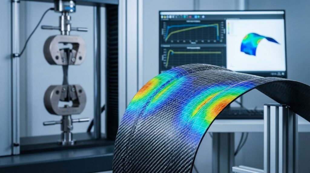
These properties are usually determined through a combination of experimental testing (e.g., ASTM standards D3039 for tension, D3410 for compression) and micromechanical modeling.
Why Composite Analysis Matters for Engineers
Accurate composite analysis is crucial for:
- Optimizing Design: Tailoring ply orientations and stacking sequences to achieve maximum performance and minimum weight.
- Predicting Performance: Ensuring the structure meets strength, stiffness, and fatigue requirements under operational loads.
- Ensuring Structural Integrity: Identifying potential failure locations and modes (e.g., fiber breakage, matrix cracking, delamination). This is especially critical in high-consequence applications like aerospace components or deep-sea oil & gas equipment.
- Reducing Prototyping: Simulation-driven design significantly cuts down the need for expensive physical prototypes and testing cycles.
Applications Across Industries
- Aerospace: Fuselages, wing components, control surfaces, engine casings.
- Oil & Gas: Risers, pipelines, pressure vessels, composite repairs for aging infrastructure (often under FFS Level 3 assessments).
- Automotive: Chassis, body panels, driveshafts in performance vehicles.
- Biomechanics: Prosthetics, orthotics, medical implants that require biocompatibility and specific mechanical responses.
- Civil Engineering: Bridge decks, reinforcement for concrete structures.
Key Challenges in Composite Analysis
Analyzing composites is inherently more complex than isotropic materials due to:
- Anisotropy: Requires advanced constitutive models and element formulations.
- Multiple Failure Modes: Unlike yielding in metals, composites can fail in various ways: fiber breakage, matrix cracking, delamination (separation between plies), buckling, or combinations thereof. Predicting these requires specific failure criteria.
- Interlaminar Stresses: Significant stresses can develop between plies, especially near free edges and discontinuities, leading to delamination.
- Manufacturing Effects: Fiber misalignment, voids, and residual stresses from curing can significantly impact actual performance.
Practical Workflow for Composite Analysis (FEA Focus)
Finite Element Analysis (FEA) is the cornerstone of modern composite analysis. Here’s a typical workflow:
Modeling Composite Layups
CAD Model Preparation
Start with a clean CAD model of your component. For shell-based composite analysis, the mid-surface representation is often used. Ensure consistent surface normal directions.
Material Definition
Define the orthotropic material properties for each individual lamina in your FEA software (e.g., Abaqus, ANSYS Mechanical, Nastran). This includes elastic moduli, shear moduli, Poisson’s ratios, and strength allowables. For advanced simulations, consider including damage initiation and propagation parameters.
Ply Stacking Sequence & Orientation
This is where the magic happens. Define the stacking sequence (e.g., [0/45/-45/90]s for a symmetric laminate) and the thickness for each ply. Crucially, specify the fiber orientation angle for each ply relative to a local or global coordinate system. Software like Abaqus’s Composite Layup, ANSYS ACP (Additive Composite Preprocessor), or MSC Patran’s laminate tools simplify this process, allowing you to visualize and verify the layup.
Element Selection
For thin-walled structures, shell elements (e.g., S4R in Abaqus, SHELL181 in ANSYS) are efficient and widely used, typically based on classical laminate theory or first-order shear deformation theory (Mindlin-Reissner). For thick laminates or regions with high interlaminar stress gradients (e.g., bolted joints, cutouts), 3D solid elements are necessary, modeling each ply as a distinct solid layer or using continuum shell elements for better through-thickness resolution. Using a hybrid approach, where appropriate, can optimize computation time.
Applying Loads & Boundary Conditions
As with any FEA, accurately define your load cases and boundary conditions. Ensure they reflect the real-world operational environment. For composites, special attention should be paid to:
- Load Introduction: How loads are transferred into the composite structure (e.g., bolted joints, bonded interfaces).
- Thermal Loads: Composites can exhibit significant anisotropy in thermal expansion, leading to internal stresses under temperature changes.
Analysis Types for Composites
Depending on the design requirements, you might perform:
- Static Structural Analysis: For strength and stiffness under steady loads.
- Buckling Analysis: Critical for thin-walled composite structures. Both linear eigenvalue buckling and non-linear post-buckling analyses are common.
- Dynamic Analysis: Modal analysis (natural frequencies and mode shapes), transient dynamics, or harmonic analysis for vibration response.
- Progressive Failure Analysis: More advanced simulations (e.g., using Hashin, Tsai-Wu, Puck, or LaRC failure criteria) that predict damage initiation and propagation, allowing for residual strength assessment after initial failure.
Post-Processing & Results Interpretation
Interpreting composite FEA results requires looking beyond global displacements and stresses. Focus on:
- Ply Stresses and Strains: Examine stresses and strains in each individual ply, resolved into the material’s local (fiber) coordinate system.
- Failure Indices: Most composite analysis tools calculate failure indices (e.g., based on Hashin, Tsai-Wu criteria). A failure index greater than 1 indicates potential failure.
- Interlaminar Shear and Normal Stresses: These are critical for predicting delamination, especially at free edges, cutouts, and load introduction points.
- Ply Delamination Prediction: Tools may offer specialized features for predicting delamination using cohesive zone modeling (CZM) or virtual crack closure technique (VCCT).
Common Software Tools for Composite Analysis
Several leading CAE packages provide robust capabilities for composite analysis:
- Abaqus: Excellent for non-linear, progressive failure analysis, and highly detailed 3D modeling of composites.
- ANSYS Mechanical/ACP: User-friendly interface for defining layups, comprehensive analysis capabilities, and strong integration with ANSYS Fluent/CFX for multiphysics.
- MSC Nastran/Patran: Long-standing industry standard, particularly strong in linear static, buckling, and dynamic analysis. Patran provides powerful pre/post-processing for Nastran.
- CATIA Composites: Integrated solution for design and manufacturing, often linked with FEA tools.
- OpenFOAM: Open-source option, often combined with custom Python or MATLAB scripts for specific composite constitutive models or optimization routines.
Need to run complex composite models but lack the hardware? EngineeringDownloads offers affordable HPC rental services to power your simulations, along with online courses and internship-style training to master these advanced tools.
Verification & Sanity Checks for Composite Models
Never trust an FEA result blindly. Rigorous verification and sanity checks are paramount for composite analysis:
Mesh Quality Assessment
Ensure your mesh is appropriate for the geometry and expected stress gradients. For shell models, aspect ratio, warpage, and Jacobian should be within acceptable limits. For 3D ply models, sufficient elements through the thickness are crucial to capture interlaminar effects. Refine mesh in critical areas like stress concentrations (holes, corners) and load introduction points.
Boundary Conditions & Load Path Review
Visually inspect applied loads and boundary conditions. Do they accurately represent the real-world scenario? Is the model over-constrained or under-constrained? Trace the load path through the structure – does it make engineering sense?
Convergence Studies
Perform a mesh convergence study to ensure your results are independent of mesh density. This involves running the analysis with progressively finer meshes and observing the change in key output parameters (e.g., maximum stress, failure index). Similarly, for non-linear analyses, check solution convergence criteria.
Validation Against Hand Calculations or Experimental Data
For simple geometries (e.g., a simply supported laminate beam under bending), compare FEA results with classical laminate theory (CLT) hand calculations. If experimental test data (e.g., from a material characterization program) is available, compare model predictions against these results. Discrepancies here often highlight issues in material properties or boundary conditions.
Sensitivity Analysis
Investigate how variations in input parameters (e.g., ply thickness, fiber orientation angle, material properties) affect your results. This helps identify critical parameters and assess the robustness of your design against manufacturing tolerances.
Troubleshooting Common Composite Analysis Issues
- Numerical Instability: Often due to highly non-linear material behavior, buckling, or poorly defined contact. Try smaller load increments, adjust convergence tolerances, or re-evaluate contact definitions.
- Unexpected Failure Modes: If the model predicts an implausible failure, re-check material properties, ply orientations, and boundary conditions. Ensure appropriate failure criteria are selected.
- Delamination at Free Edges: This is a common phenomenon. If not explicitly modeled with CZM, use interlaminar stress components (σz, τxz, τyz) to assess risk. Consider tailoring plies or adding edge reinforcement.
- Solution Times: Complex 3D models with many plies and non-linear effects can be computationally expensive. Optimize element types, use sub-modeling for local detail, and leverage parallel computing.
Tips for Robust Composite Designs
- Ply Drop-Offs: Manage ply drop-offs carefully to avoid stress concentrations. Tapering and staggering can mitigate this.
- Material Selection: Choose the right fiber and matrix system for the application’s environment (temperature, chemical exposure, impact).
- Ply Optimization: Explore different stacking sequences and fiber orientations to optimize for multiple criteria (strength, stiffness, weight, cost). Python or MATLAB scripting can automate parametric studies for optimization.
- Manufacturing Considerations: Always design with manufacturability in mind. Complex ply layups can be difficult and costly to produce.
Actionable Takeaways & Checklist
To ensure a successful composite analysis project:
- ✓ Clearly define your analysis objectives and performance criteria.
- ✓ Source reliable, experimentally derived material properties for each ply.
- ✓ Carefully define ply stacking sequences and fiber orientations.
- ✓ Select appropriate element types (shells for thin, solids for thick/interlaminar details).
- ✓ Apply realistic loads and boundary conditions.
- ✓ Perform rigorous mesh sensitivity and convergence studies.
- ✓ Validate results against simplified models or test data.
- ✓ Interpret results beyond global values, focusing on ply-level stresses and failure indices.
- ✓ Consider progressive failure analysis for critical components.
Further Reading
For a deeper dive into the theoretical mechanics of composite materials, consider resources from reputable academic institutions:
MIT OpenCourseWare – Mechanics of Composite Materials Lecture Notes