Introduction to ANSYS CFX: A CFD Powerhouse
In the realm of Computational Fluid Dynamics (CFD), ANSYS CFX stands as a venerable and highly capable solver, renowned for its robustness, accuracy, and efficiency across a broad spectrum of fluid flow applications. Developed with a focus on turbomachinery, multiphase flows, and complex heat transfer, CFX offers engineers a powerful tool within the ANSYS Workbench environment for simulating intricate fluid phenomena. Unlike some other CFD codes that employ a cell-centered finite volume approach, CFX utilizes an element-based finite volume method, often contributing to its stability and faster convergence for certain classes of problems, particularly those involving rotating machinery.
For engineers engaged in product design, performance optimization, or failure analysis across industries such as Aerospace, Oil & Gas, Power Generation, and Biomechanics, a deep understanding of CFX capabilities is paramount. This guide provides a professional, engineer-to-engineer perspective on leveraging CFX for high-fidelity CFD simulations, emphasizing actionable insights and practical methodologies.
Core Capabilities and Applications of CFX
ANSYS CFX distinguishes itself through a suite of advanced models and numerical techniques tailored for specific challenging fluid dynamics problems.
Fluid Flow Regimes and Physics
CFX is adept at modeling various flow regimes and physical phenomena:
- Turbulent Flows: Offers a comprehensive array of turbulence models, including RANS (e.g., k-epsilon, k-omega SST, BSL), LES, and DES, allowing engineers to select the most appropriate model for accuracy and computational cost. The SST (Shear Stress Transport) model, for instance, is highly regarded for its ability to accurately predict flow separation under adverse pressure gradients, making it a go-to for aerodynamic and hydraulic applications.
- Laminar Flows: For low Reynolds number flows where viscous forces dominate.
- Compressible and Incompressible Flows: Handles flows ranging from low-speed incompressible systems to high-speed compressible flows with shocks.
- Heat Transfer: Includes conductive, convective, and radiative heat transfer models. Conjugate Heat Transfer (CHT) capabilities are particularly strong, allowing for seamless coupling between fluid and solid domains.
Multiphase Flow Modeling
CFX excels in modeling complex multiphase systems, which are critical in many industrial processes:
- Eulerian-Eulerian Model: Ideal for modeling interpenetrating continua, such as gas-liquid or liquid-solid suspensions, where both phases are treated as fluids.
- Eulerian-Lagrangian (Particle Transport) Model: Suitable for dilute particulate flows, where individual particles (solids, droplets, bubbles) are tracked through a continuous fluid phase.
- Free Surface Flows: Utilizes the Homogeneous Multiphase model or Volume of Fluid (VOF) techniques for capturing interfaces between immiscible fluids, relevant for sloshing, wave dynamics, or filling processes.
Key Multiphase Models in CFX
The selection of the correct multiphase model is critical. For illustrative purposes:
- For a gas-liquid stirred tank reactor, an Eulerian-Eulerian approach with appropriate interphase transfer models (drag, mass transfer) is typically chosen.
- For erosion prediction due to solid particles in a pipe, an Eulerian-Lagrangian approach with wall erosion models would be employed.
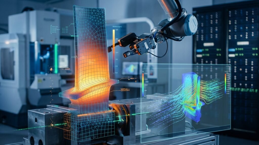
Turbomachinery Analysis
CFX’s heritage in turbomachinery applications is evident in its specialized features:
- Blade Row Modeling: Advanced mixing plane interfaces (e.g., Stage, Frozen Rotor) for simulating steady-state interactions between rotating and stationary components without the computational cost of full transient simulations.
- Transient Rotor-Stator (TRS): For capturing time-accurate, transient interactions between blade rows, crucial for aeroacoustics and unsteady loading.
- Automatic Mesh Generation for Blades: Streamlined workflows for turbomachinery specific meshing.
Heat Transfer and Conjugate Heat Transfer (CHT)
Effective thermal management is crucial in many engineering systems. CFX provides robust tools for:
- Modeling heat transfer within fluids and solids.
- Seamlessly coupling fluid and solid domains for accurate CHT analysis, where heat exchange occurs at the fluid-solid interface. This is vital for heat exchangers, electronic cooling, and engine component thermal management.
Reacting Flows and Combustion
For applications involving chemical reactions and combustion, CFX offers:
- Mixture Fraction/PDF Models: For non-premixed and partially premixed combustion.
- Eddy-Dissipation/Finite-Rate Chemistry: For modeling reaction rates in turbulent reacting flows.
- Detailed Chemical Kinetics: Integration with external chemistry solvers for complex reaction mechanisms.
Applications Across Industries
CFX’s versatility makes it indispensable across various sectors:
- Aerospace: Aerodynamic performance of wings, propulsion systems, turbine and compressor design, environmental control systems.
- Oil & Gas: Multiphase flow in pipelines, separation technologies, flow assurance, mixing processes in reactors, flare stack design.
- Automotive: Under-hood thermal management, HVAC, combustion in engines, vehicle aerodynamics.
- Power Generation: Steam turbines, gas turbines, boilers, heat exchangers, cooling towers.
- Biomechanics: Blood flow in arteries, prosthetic device design, drug delivery systems.
Practical Workflow for ANSYS CFX Simulations
A systematic approach is key to successful CFD simulations with CFX. The following outlines a typical workflow:
Step 1: Geometry Preparation and Meshing
The foundation of any accurate CFD simulation is a clean geometry and a high-quality mesh.
- CAD Integration: Import geometry from CAD systems (e.g., CATIA, SolidWorks) into ANSYS SpaceClaim or DesignModeler. Simplify the geometry by removing small features, chamfers, or fillets that are irrelevant to the fluid flow but can complicate meshing. Define the fluid domain and, for CHT, the solid domain.
- Meshing in ANSYS Meshing: Generate a high-quality computational mesh. For complex geometries, a hybrid mesh (e.g., hexahedral core with tetrahedral boundary layers) often provides a good balance of accuracy and computational cost.
Meshing Best Practices for CFX
- Boundary Layers: Ensure sufficient inflation layers (e.g., 10-20 layers) near walls to accurately resolve the viscous sublayer and capture wall-bounded turbulence. Aim for a y+ value appropriate for your chosen turbulence model (typically y+ < 5 for low-Reynolds models like SST or 30 < y+ < 300 for wall-function based models).
- Element Quality: Prioritize orthogonal quality, aspect ratio, and skewness. CFX is robust, but poor mesh quality can hinder convergence and accuracy.
- Mesh Sizing: Refine the mesh in regions of high gradients (e.g., wakes, shear layers, near inlets/outlets, around sharp corners) and coarsen where flow is relatively uniform to optimize cell count.
Step 2: Physics Setup in CFX-Pre
Once the mesh is generated, define the physics in CFX-Pre.
- Domain Definition: Specify fluid and solid domains. Assign fluid properties (density, viscosity, thermal conductivity, specific heat) and material properties for solids.
- Turbulence Model Selection: Choose an appropriate turbulence model based on the flow characteristics (e.g., k-epsilon for general industrial flows, k-omega SST for flows with separation or adverse pressure gradients, such as in turbomachinery).
- Heat Transfer Model: Enable total energy or thermal energy equations, and specify radiation models if required.
- Multiphase Models: If applicable, select the appropriate multiphase model (e.g., Homogeneous, Eulerian-Eulerian) and define phase properties and interphase transfer mechanisms.
Defining Boundary Conditions: A Critical Step
Accurate boundary conditions (BCs) are paramount for meaningful results. Incorrect BCs are a common source of simulation errors.
| Boundary Condition Type | Typical Application | Key Parameters to Define |
|---|---|---|
| Inlet | Flow entering the domain (e.g., pipe inlet, fan intake) | Mass flow rate, velocity (magnitude & direction), total pressure, total temperature, turbulence intensity/length scale. |
| Outlet | Flow exiting the domain (e.g., pipe outlet, diffuser exit) | Static pressure (relative or absolute), mass flow rate (if specified), average static pressure. |
| Wall | Solid surfaces confining the fluid | No-slip (default), wall roughness, heat flux, wall temperature, adiabatic. |
| Symmetry | Planes of symmetry in the flow field | No flow/scalar flux across the boundary. Reduces computational domain. |
| Opening | Boundary where flow can enter or exit freely based on pressure difference | Static pressure, flow direction, temperature (for inflow). |
Step 3: Solver Control and Convergence Criteria
Configure the solver settings for efficient and accurate computation:
- Solver Type: CFX uses an implicit solver by default, offering robust convergence for steady-state and transient problems.
- Time Stepping: For transient simulations, define a suitable physical time step and number of inner loops. For steady-state, use false time-stepping for accelerated convergence.
- Convergence Criteria: Set appropriate residual targets (e.g., RMS residuals of 10-5 or 10-6 for momentum and continuity, 10-7 for energy). Monitor imbalances for global quantities like mass and energy to ensure overall conservation.
- Monitor Points: Define expressions or points within the domain to track key engineering quantities (e.g., pressure drop, forces, temperatures) during the solution process. This provides real-time insight into solution stability and convergence.
Step 4: Post-Processing and Results Interpretation (CFX-Post)
After the solution converges, use CFX-Post to visualize and extract meaningful data.
- Visualization: Generate contours of pressure, velocity, temperature; plot streamlines to visualize flow paths; create vector plots to show flow direction and magnitude.
- Quantitative Data: Extract numerical data such as pressure drops, mass flow rates through specific cross-sections, forces and moments on surfaces, and average/min/max values of variables. Create charts and reports for presentation.
- Animations: For transient simulations, create animations to observe time-dependent phenomena.
Verification and Sanity Checks in CFX
Robust CFD practice demands rigorous verification and validation (V&V) to build confidence in simulation results.
Mesh Independence Study
This is a fundamental verification step. Perform simulations on at least three different mesh resolutions (coarse, medium, fine). If the key engineering results (e.g., pressure drop, drag coefficient, average temperature) do not change significantly between the medium and fine meshes, the solution is considered mesh-independent. If results are still changing, further refinement is necessary.
Boundary Condition Sensitivity Analysis
Slight variations in inlet conditions (e.g., small changes in velocity magnitude or turbulence intensity) or outlet pressure can sometimes lead to notable changes in results. Conducting a sensitivity study helps understand the robustness of your model and the impact of input uncertainties. For illustrative purposes, varying an inlet velocity by ±5% and observing the change in pressure drop can offer valuable insights.
Convergence Monitoring
Beyond meeting residual targets, ensure that integral quantities (e.g., mass flow rate imbalance, heat flux imbalance) are also converging to acceptable levels (typically <1%). Monitor your defined output parameters; if they fluctuate significantly at the end of the simulation, the solution may not be fully converged, even if residuals are low.
Validation with Analytical Solutions or Experimental Data
Whenever possible, validate your CFX model against known analytical solutions for simplified cases or, more importantly, against experimental data for similar geometries or operating conditions. This step is crucial for establishing the predictive capability of your simulation setup. For example, comparing simulated pressure drop in a simple pipe flow with established correlations like the Darcy-Weisbach equation.
Physical Plausibility
Always apply engineering judgment. Do the results make physical sense? Are velocities higher where expected? Is the temperature distribution logical? Unexpected flow patterns, unrealistic magnitudes of variables, or non-conservation of mass/energy often point to an error in geometry, meshing, or boundary conditions.
Advanced Topics and Integration
FSI (Fluid-Structure Interaction) with ANSYS Mechanical
For problems where fluid forces deform solid structures, or structural deformation influences fluid flow, CFX can be coupled with ANSYS Mechanical. This FSI capability is vital in fields like aerospace (aeroelasticity), biomechanics (cardiovascular devices), and turbomachinery (blade vibration). ANSYS Workbench facilitates easy setup of one-way (fluid forces on structure) or two-way (iterative exchange of forces and displacements) FSI simulations.
Optimization and Parametric Studies
Leverage ANSYS Workbench’s DesignXplorer to conduct parametric studies, sensitivity analyses, and design optimization. This allows engineers to systematically explore design variations, identify optimal geometries, or determine the impact of operating conditions without manual re-runs. Python or MATLAB scripting can also be used to drive parametric studies by interacting with CFX input files and post-processing results.
Scripting and Automation (Python/MATLAB)
For repetitive tasks, complex workflows, or integrating CFX into larger design ecosystems, scripting is invaluable. CFX-Pre and CFX-Post sessions can be journaled and replayed, or driven via the ANSYS Workbench Journaling feature. Advanced users can utilize Python or MATLAB to:
- Automate geometry creation or modification via SpaceClaim/DesignModeler APIs.
- Programmatically generate and modify CFX input files (.def).
- Automate solver runs and monitor convergence.
- Extract and process results from CFX-Post for custom analysis and reporting.
EngineeringDownloads.com offers a range of downloadable templates and Python scripts tailored for automating common CFD tasks, which can significantly enhance your CFX workflow efficiency.
Key Takeaways for Effective CFX Usage
Mastering ANSYS CFX demands a combination of theoretical knowledge and practical experience. Focus on:
- Fundamental Fluid Dynamics: A strong grasp of fluid mechanics, heat transfer, and turbulence theory is non-negotiable for informed model selection and interpretation.
- Geometry and Mesh Quality: Dedicate sufficient time to preparing clean geometry and generating a high-quality, resolution-appropriate mesh. This is the single most impactful step for solution accuracy and convergence.
- Appropriate Model Selection: Understand the assumptions and limitations of different physical models (e.g., turbulence, multiphase, combustion) and choose them judiciously for your specific application.
- Rigorous V&V: Never skip mesh independence studies, sensitivity analyses, and where possible, validation against experimental data.
- Post-Processing Acumen: Learn to effectively extract and interpret data, not just visualize pretty pictures. Relate CFD outputs back to engineering performance metrics.
For engineers seeking to deepen their expertise in ANSYS CFX or tackle particularly challenging CFD problems, expert tutoring and online consultancy services are available through EngineeringDownloads.com, providing tailored guidance and advanced problem-solving strategies.