Aerospace Engineering is a captivating field dedicated to the design, development, construction, testing, and operation of aircraft and spacecraft. It’s where cutting-edge science meets practical application, pushing the boundaries of what’s possible in air and space.
From commercial airliners safely transporting millions daily to satellites orbiting Earth and probes exploring distant planets, aerospace engineers are at the forefront of innovation. This discipline demands a deep understanding of physics, mathematics, materials science, and computational methods, making it one of the most intellectually stimulating engineering fields.
In this comprehensive guide, we’ll explore the core principles of aerospace engineering, delve into essential analysis techniques like FEA and CFD, discuss practical workflows, and highlight the tools that drive progress in this dynamic industry. Whether you’re a student, a practicing engineer, or simply curious, get ready to elevate your understanding.

Image: Close-up of a modern aircraft engine’s fan blades, illustrating complex aerospace components.
Diving Deep into Aerospace Disciplines
Aerospace engineering is a broad field, encompassing several specialized areas. Understanding these disciplines is key to appreciating the complexity and synergy involved in developing aerospace vehicles.
Aerodynamics & Fluid Dynamics
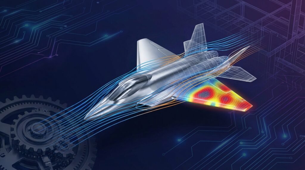
This discipline focuses on the study of how air (or other fluids) interacts with moving objects. For aircraft, this involves understanding lift, drag, thrust, and stability. For spacecraft, it includes high-speed atmospheric re-entry and plume interactions in a vacuum.
- Lift Generation: Designing wing profiles (airfoils) to efficiently generate lift.
- Drag Reduction: Streamlining vehicle shapes to minimize resistance.
- Stability & Control: Ensuring the vehicle remains stable and controllable during flight.
Computational Fluid Dynamics (CFD)
CFD is an indispensable tool in aerodynamics. It uses numerical methods and algorithms to simulate fluid flow, heat transfer, and related phenomena. Software like ANSYS Fluent, ANSYS CFX, and OpenFOAM allow engineers to predict aerodynamic performance, optimize designs, and troubleshoot flow issues without extensive physical testing.
Practical Tip: When setting up CFD simulations for aerospace, always prioritize mesh quality around critical aerodynamic surfaces and ensure proper turbulence modeling for realistic flow predictions.
Structural Engineering & Materials
Aerospace structures must be incredibly strong yet lightweight to withstand extreme loads during flight and launch. This involves meticulous material selection and structural design to ensure integrity.
- Lightweight Design: Utilizing advanced composites (carbon fiber, fiberglass), aluminum alloys, and titanium.
- Load Path Analysis: Understanding how forces distribute through the structure.
- Vibration & Flutter: Analyzing dynamic responses to prevent resonance and catastrophic failures.
Finite Element Analysis (FEA)
FEA is critical for validating structural designs. Tools like Abaqus, ANSYS Mechanical, and MSC Nastran/Patran enable engineers to simulate stress, strain, deformation, and fatigue under various operating conditions. This allows for optimization of material usage and prediction of failure points.
Fatigue & Fracture Mechanics
Aerospace components are subjected to millions of load cycles throughout their operational life. Understanding fatigue crack initiation and propagation, along with fracture toughness, is paramount for ensuring long-term structural integrity and flight safety. FFS (Fitness-for-Service) assessments, often at Level 3, are routinely performed for critical components.
Propulsion Systems
This area deals with the design and performance of engines that generate thrust. For aircraft, it’s typically jet engines (turbofan, turbojet). For spacecraft, it involves rocket engines (liquid, solid, hybrid) and advanced propulsion concepts.
- Thrust Generation: Optimizing engine cycles for efficiency and power.
- Thermal Management: Designing components to withstand extreme temperatures.
- Fuel Efficiency: Maximizing range and reducing operational costs.
Flight Mechanics & Control
This discipline focuses on the motion of aerospace vehicles and the systems that control them. It involves stability analysis, control system design, and navigation.
- Stability Analysis: Ensuring the vehicle naturally returns to a stable state after a disturbance.
- Control System Design: Developing autopilots, fly-by-wire systems, and attitude control systems for spacecraft.
- Navigation: Utilizing GPS, inertial navigation systems (INS), and other sensors.
Manufacturing & Production
Turning complex designs into physical reality requires specialized manufacturing processes, quality control, and assembly techniques tailored for aerospace materials and tolerances.
- Additive Manufacturing: 3D printing of complex geometries for lightweight components.
- Precision Machining: High-tolerance machining of critical parts.
- Advanced Joining Techniques: Welding, riveting, bonding for diverse materials.
Avionics & Systems Integration
Avionics refers to the electronic systems used on aircraft and spacecraft, including communication, navigation, flight control, and radar. Systems integration ensures all these complex subsystems work together harmoniously and reliably.
The CAD-CAE Workflow in Aerospace
Modern aerospace engineering relies heavily on Computer-Aided Design (CAD) and Computer-Aided Engineering (CAE) tools to accelerate the design-analysis-optimization cycle. This integrated workflow is essential for handling the complexity and stringent requirements of aerospace projects.
Design Phase
The process often begins with conceptual design, followed by detailed 3D modeling using CAD software. Tools like CATIA are industry standards, allowing engineers to create precise geometries, assemble complex systems, and define manufacturing features.
- Conceptual Design: Sketching initial ideas and preliminary layouts.
- Detailed Modeling: Creating accurate 3D models of components and assemblies.
- Parametric Design: Using parameters to easily modify designs and explore variations.
Analysis Phase
Once the design is modeled, it moves into the CAE phase for various simulations.
FEA Workflow
For structural analysis, engineers prepare the CAD model for FEA by simplifying geometry, creating a mesh, and defining material properties, boundary conditions, and loads. This often involves pre-processing tools like MSC Patran or the pre-processors within Abaqus or ANSYS Mechanical.
CFD Workflow
For aerodynamic analysis, the CAD model is similarly prepared for CFD. This involves generating a fluid volume, creating a high-quality mesh (often with prism layers near surfaces), and defining inlet/outlet conditions, turbulence models, and solver settings in tools like ANSYS Fluent or OpenFOAM.
Optimization & Iteration
Simulation results feed back into the design process. Engineers identify areas for improvement (e.g., stress concentrations, excessive drag, weight reduction opportunities) and iterate on the design. This iterative loop, often supported by optimization algorithms, is crucial for achieving peak performance and efficiency.
Practical Simulation Workflow for Structural Integrity
Let’s walk through a typical workflow for conducting a structural integrity analysis using FEA, focusing on aerospace components.
Step 1: Problem Definition
Clearly define the objective of the simulation. What specific loads will the component experience? What failure modes are you trying to predict (e.g., yielding, buckling, fatigue)? What are the acceptable safety margins?
- Example: Analyze the stress distribution in an aircraft wing spar under maximum flight load and ensure it meets design strength requirements.
Step 2: Geometry & Meshing
Import or create the CAD geometry. Simplify non-critical features to reduce computational cost without sacrificing accuracy. Generate an appropriate finite element mesh.
- Meshing Tip: Use finer meshes in areas of high stress gradients (e.g., fillets, holes, load application points) and coarser meshes elsewhere. Employ elements suitable for the geometry (e.g., shell elements for thin structures, solid elements for bulky parts).
Step 3: Material Models & Boundary Conditions
Assign realistic material properties (Young’s Modulus, Poisson’s Ratio, Yield Strength) to your model. Define boundary conditions that accurately represent how the component is constrained and loaded in the real world.
Example Boundary Conditions for a Wing Spar Analysis:
| Type of Constraint/Load | Description | Typical Application |
|---|---|---|
| Fixed Supports | Restrain all degrees of freedom (DOF) at attachment points. | Where the spar connects to the fuselage or other rigid structures. |
| Displacement Constraints | Allow movement in specific directions, constrain others. | Symmetry planes, sliding contacts. |
| Pressure Loads | Apply distributed load over a surface. | Aerodynamic pressure on the wing skin transferred to the spar. |
| Concentrated Forces/Moments | Apply load at a specific node or element face. | Engine weight, landing gear loads transferred via fasteners. |
| Gravity Load | Apply body force due to gravity. | Always relevant for large structures. |
Step 4: Solver Setup & Execution
Select the appropriate analysis type (e.g., static structural, modal, fatigue). Configure solver parameters, such as solution controls, convergence criteria, and output requests. Run the simulation using software like Abaqus or ANSYS Mechanical.
Step 5: Post-Processing & Interpretation
Visualize the results (stress contours, deformation plots). Extract quantitative data (maximum stress, minimum factor of safety). Compare results against design criteria and material limits. Identify potential failure points and areas for design optimization.
Actionable Insight: Don’t just look at maximum stress. Analyze stress paths, identify stress concentrations, and consider if your simplifications or boundary conditions might be introducing artificial stress risers.
Verification & Sanity Checks in Aerospace Analysis
Simply running a simulation isn’t enough; robust verification and validation are essential to trust your results.
Mesh Sensitivity
Perform a mesh refinement study to ensure your results are independent of mesh density. Run the simulation with progressively finer meshes and observe if critical results (e.g., peak stress, displacement) change significantly. If results stabilize, your mesh is sufficiently refined.
Convergence Criteria
For non-linear simulations, monitor the solver’s convergence. Ensure residual forces or displacements fall below acceptable tolerances. Non-convergence indicates a problem with the model setup (e.g., unstable contacts, incorrect material properties, insufficient boundary conditions).
Boundary Condition Validation
Are your applied loads and constraints realistic? Consider if any assumptions about fixed supports or applied pressures could be overly simplistic. A slight change in a boundary condition can sometimes drastically alter results.
Hand Calculations & Benchmarking
Wherever possible, perform simplified hand calculations (e.g., beam theory, plate theory) for critical sections to get an order-of-magnitude estimate of expected stresses or deflections. Compare your FEA results to these simplified models or to published benchmark problems to build confidence.
Sensitivity Analysis
Explore how variations in input parameters (material properties, load magnitudes, geometric tolerances) affect your results. This helps understand the robustness of your design and identify critical parameters that require tight control.
Leveraging Python & MATLAB for Aerospace Engineering
Scripting languages are invaluable for automating tasks, processing data, and developing custom tools in aerospace engineering.
Automation & Scripting
Python and MATLAB can automate repetitive tasks in pre-processing (e.g., modifying CAD models, generating complex meshes), solver setup, and post-processing. Many commercial FEA/CFD software packages offer Python APIs (Application Programming Interfaces) for scripting.
Data Analysis & Post-Processing
After a simulation, you often end up with vast amounts of data. Python (with libraries like NumPy, SciPy, Matplotlib, Pandas) and MATLAB are excellent for filtering, analyzing, and visualizing this data to extract meaningful insights and create custom reports.
Control System Design
MATLAB and Simulink are widely used for designing, simulating, and validating control systems for aircraft and spacecraft, including flight control laws, autopilots, and attitude control systems.
Illustrative Example: Scripting FEA Post-Processing
Imagine you have 50 FEA models, each representing a slight design variation of a bracket, and you need to extract the maximum principal stress from a specific region for all of them. Manually opening each result file and navigating to the correct region is tedious. A Python script can:
- Iterate through all result files in a directory.
- Open each result file using the FEA software’s API.
- Identify the region of interest.
- Extract the maximum principal stress.
- Store the data in a CSV file for further analysis.
This kind of automation saves countless hours and minimizes human error. Need help with scripting or setting up your analysis workflows? EngineeringDownloads.com offers expert tutoring and online consultancy services to optimize your engineering processes.
Common Challenges & How to Overcome Them
Aerospace engineering, while rewarding, presents unique challenges.
Complexity of Systems
Aerospace vehicles are highly integrated systems with numerous interacting components. Managing this complexity requires robust systems engineering approaches, modular design, and thorough integration testing.
Computational Cost
High-fidelity simulations (especially for large assemblies or complex fluid dynamics) can be computationally expensive, requiring significant hardware and time. Overcoming this involves intelligent model simplification, parallel computing, and efficient meshing strategies.
Material Non-Linearity
Many advanced aerospace materials exhibit non-linear behavior (plasticity, creep, hyperelasticity) under operational conditions. Accurate modeling of these behaviors is crucial for predictive accuracy but adds complexity to simulations. This requires advanced material models and robust non-linear solver techniques.
Regulatory Compliance
Aerospace products are subject to stringent regulations (e.g., FAA, EASA). Demonstrating compliance through extensive testing, analysis, and documentation is a major undertaking. A well-documented, verifiable simulation workflow is critical here.
Career Pathways & Future Trends
Career Roles
Aerospace engineers can find roles in diverse areas:
- Design Engineer: Creating new aircraft/spacecraft components or systems.
- Stress Analyst: Performing FEA to ensure structural integrity.
- Aerodynamics Engineer: Conducting CFD simulations and wind tunnel tests.
- Propulsion Engineer: Designing and testing engines.
- Systems Engineer: Overseeing the integration of various subsystems.
- Flight Test Engineer: Planning and executing flight tests.
- Manufacturing Engineer: Optimizing production processes.
Emerging Technologies
The field is constantly evolving, with exciting trends shaping its future:
- Sustainable Aviation: Electric and hybrid-electric propulsion, sustainable aviation fuels.
- Urban Air Mobility (UAM): Development of eVTOL (electric Vertical Take-Off and Landing) aircraft.
- Hypersonic Flight: Pushing the boundaries of speed for both civilian and military applications.
- Space Commercialization: Growth in private spaceflight, satellite constellations, and lunar/Mars exploration.
- Advanced Materials: Further development of composites, smart materials, and additive manufacturing.
- Digital Twins: Real-time simulation models linked to physical assets for predictive maintenance and performance monitoring.
Aerospace engineering is a field of constant innovation, offering challenges and opportunities that inspire engineers to reach for the stars, literally and figuratively.
Further Reading
For more detailed information on aerospace structural design, refer to authoritative academic resources or industry standards, such as those published by NASA or professional organizations. A good starting point for detailed engineering mechanics related to aerospace structures can be found via official university materials or reputable engineering handbooks, for example, the comprehensive resources from NASA Aerospace Publications.