

Additive manufacturing (often called 3D printing) and traditional welding are both processes that involve melting and fusing material. These processes offer incredible possibilities (from printing intricate medical implants to welding critical oil-and-gas pipelines), but they also introduce challenges like residual stresses, distortion/warping, and complex thermal histories. Finite Element Analysis (FEA) has become an indispensable tool to simulate and tackle these challenges before any metal is melted in real life. In this comprehensive guide, we’ll explore how FEA is used to simulate additive manufacturing and welding in software like Abaqus and ANSYS, discuss key techniques (such as the Goldak heat source model), highlight applications across industries (oil & gas, aerospace, medical, etc.), and even see how AI/Machine Learning (ML) is enhancing these simulations. We’ll keep the tone friendly and approachable – like one engineer talking to another – while delivering the depth you need to stay ahead. Let’s dive in!
Why Simulate Additive Manufacturing and Welding Processes?
Both AM and welding involve highly thermal-mechanical processes: intense localized heating, melting, and subsequent cooling/solidification. This produces complex effects in the material:
- Residual Stresses & Distortion: When a welded part cools down, it can lock in residual stresses and sometimes warp out of shape. The performance and safety of a weld (or a 3D-printed part) depend heavily on controlling these effects. For example, in a welded structure (like a submarine hull or a pipeline), improper heat input might lead to high tensile residual stresses that could later cause cracking. In a 3D printed aerospace bracket, uneven cooling might cause the part to warp (so it doesn’t fit as designed). Simulation allows engineers to predict these outcomes before they happen in production.
- Microstructure and Properties: The thermal cycling in welding/AM (rapid heating and cooling, multiple passes or layers) affects microstructure (like grain size, phase composition) which in turn affects material properties. While detailed microstructural prediction often requires advanced models, the temperature history and cooling rates from an FEA simulation give insight into where brittle phases or weak spots might form.
- Complex Geometry and Process Parameters: Additive manufacturing enables geometries that were impossible before – e.g. lattice structures in medical implants or internal cooling channels in aerospace components. But these complex shapes can also cool unevenly or have support structure challenges. Simulation helps optimize the printing process (scan paths, support placement, etc.) for such geometries. In welding, complex groove designs or multi-pass sequences can be tested in FEA to find an optimal welding sequence that minimizes distortion.
In short, FEA simulation serves as a “virtual test lab”. Rather than relying on trial-and-error with costly materials and machine time, engineers use simulation to anticipate problems: will this 3D printed part warp? Will this weld introduce too high a stress in the corner of a joint? By answering these questions virtually, one can adjust the design or process parameters proactively.
Regulatory and safety considerations also make simulation important. Industries like aerospace and oil & gas have strict standards (e.g. ASME codes for pressure vessels) that require demonstrating the integrity of welds and printed parts. Simulation provides data (like stress distribution, deformation) to ensure the part will meet these standards or to refine it until it does.
Finally, there’s an economic incentive: “first-time-right” manufacturing. Especially for metal additive manufacturing, each build can be expensive and time-consuming. Simulation helps get the process right the first time, reducing wasted builds. (As an engineer, there are few things more heartbreaking than pulling a distorted, failed build out of a metal 3D printer after tens of hours of printing!)
Overview of Additive Manufacturing Processes (and Their Simulation Challenges)
Additive manufacturing encompasses a family of processes (often categorized into seven main types). The most common methods relevant to structural metal parts include:
- Powder Bed Fusion (PBF): A laser or electron beam selectively fuses metallic powder spread in layers. Examples: SLM (Selective Laser Melting), SLS (Selective Laser Sintering for polymers), EBM (Electron Beam Melting). Simulation challenges: Very high thermal gradients, layer-by-layer addition, often needing very fine mesh to capture melt pool dynamics. Key issues are predicting part warping, residual stress, and areas of incomplete fusion. In simulation, one typically models the moving heat source (laser/beam) and progressive addition of powder material with each layer. (More on how we handle that in FEA later!)
- Directed Energy Deposition (DED): A laser (or arc/plasma) plus metal feedstock (powder or wire) build up a part by depositing material where needed, often on an existing substrate. Think of it like “robotic welding” that can 3D print new material onto a base. Simulation challenges: Similar to welding – a moving heat source adding material, but possibly covering larger volumes than PBF. We need to simulate multiple layers, sometimes with cooling pauses between layers. DED is popular for repairs (adding material to worn parts) and for large structural components. For example, Laser DED was used to print a section of a hip implant in an Abaqus simulation case, including adding material layer by layer and accounting for the laser heat input.
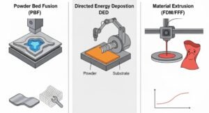
- Material Extrusion (FDM/FFF): A nozzle extrudes molten thermoplastic (in consumer 3D printers) or even semi-solid polymers/ceramics in industry. Simulation: Mostly relevant for polymers – involves thermal contraction and warping (ever had a 3D-printed ABS part curl off the print bed? Simulation can predict that). This often uses simpler analysis since polymers have lower conductivity and no phase change melting in the simulation (we just simulate thermal expansion/contraction).
- Binder Jetting, Material Jetting, Vat Photopolymerization, Sheet Lamination, etc.: These are other AM types. They have their own quirks (e.g. binder jetting involves an post-print sintering step that could deform parts; vat photopolymerization involves curing-induced stresses, etc.). In this blog, our focus is on processes involving significant thermal effects (since welding and metal AM share a lot of simulation similarity there). However, the general approach of FEA simulation – predicting distortions, stresses, etc. – applies to those as well.
From a simulation standpoint, metal additive processes like PBF and DED are very akin to welding, just automated and repeated many times. In fact, one form of metal AM, Wire-Arc Additive Manufacturing (WAAM), essentially uses a welding arc as the heat source to fabricate a part layer by layer (imagine a robot arm welding beads on top of each other to form a shape). WAAM and traditional welding both involve a moving heat source, melting filler metal, and deposition of material – so the simulation techniques are closely related.
Key simulation challenges in AM:
- Layer Activation: We must add new material in the model as printing progresses. If we were to mesh the whole part from the start, we need a way to “activate” elements layer by layer in sync with the toolpath.
- Moving Heat Source: A concentrated heat input (laser or arc) moves across the part. Capturing its effect requires either moving a heat flux load in time or using clever techniques (more on that soon).
- Thermal Cycles: Each layer may experience multiple heating/cooling cycles (as subsequent layers are added on top). Simulation must accumulate these effects, which can be computationally intense.
- Large Number of Time Steps: A detailed AM simulation might simulate hundreds or thousands of time increments to cover each small movement of the heat source over potentially hundreds of layers. This is computationally heavy, so often simulations simplify or lump some layers together when possible.
Despite these challenges, modern FEA tools and computing power have advanced to tackle AM simulation. As we’ll see, software vendors have introduced special features to make AM simulation easier for engineers.
Welding Simulation Fundamentals (FEA Approach)
If you understand what we’ve described for AM, you already understand welding simulation – it’s essentially the same physics, but usually for joining two or more parts rather than building a new part from scratch. The goal is to predict the weld-induced residual stresses, distortions, and sometimes microstructural effects on the joined parts.
Typical welding simulation scenarios: – Welding a plate or pipe (maybe multi-pass welding on a thick section). – Welding dissimilar materials (need to capture different thermal properties). – Heat-affected zone (HAZ) formation – a region that gets hot enough to alter microstructure but not melt – which can be important for properties. For practical examples you can check our welding package.

FEA simulation of welding also uses a moving heat source and often the concept of element birth and death or activation (similar to adding layers in AM). For example, in an analysis you might “activate” filler material elements in the joint as the weld progresses.
Sequential Thermal-Stress Analysis: Both welding and AM simulations usually split the problem into two analyses: 1. A transient thermal analysis that simulates the moving heat source over time, capturing temperature distribution and history. 2. A structural stress analysis that takes the thermal results (temperature vs. time for each point) and computes stresses and deformations as the material expands, contracts, and possibly yields.
This is known as a sequentially coupled thermomechanical simulation. In practice, you run the heat transfer first, then feed the temperature output into a stress/displacement analysis. This approach is common because it’s easier and often sufficiently accurate: the thermal problem is solved independently, then those temperature loads drive the mechanical problem. (Fully coupled thermomechanical simulations, where stress can also affect heat transfer, are possible but not usually necessary for welding/printing basics – temperature drives the process predominantly.)
FEA software like Abaqus, ANSYS, etc., facilitate this by allowing a transfer of results from a heat transfer step to a structural step. For instance, Abaqus has predefined procedures for sequential analysis, and ANSYS uses a similar concept (often via APDL coding or Workbench transient thermal to static structural coupling).
During the thermal analysis, we must simulate: – The progressive addition of material (newly deposited weld or new printed layer doesn’t exist at time zero – so we add it at the correct time). – The moving heat input (a weld torch or laser moving along a path depositing heat). – Heat losses (cooling to ambient via convection, radiation, etc., which might change as the part grows).
During the structural analysis: – We apply the temperature history to the model (either as a temperature-vs-time load on each element, or by reading a results file). – Again, we add new material elements as they “solidify” and become part of the structure, because before being deposited, that material isn’t providing any structural support. – As new material is added and cools, we calculate the strains and stresses. The first time a hot bead fuses to a cooler plate, the cooling will shrink the bead and maybe bend the plate – the simulation captures that. Multiple passes/layers lead to accumulation of residual stresses layer upon layer.
The “birth and death” (element activation) technique is central to these simulations. In many FEA codes, you can define elements that start inactive (essentially not in the model or with their stiffness set near zero), and then activate them at a certain time. This corresponds to feeding new material. Modern tools have made this easier: for example, Abaqus’s AM Modeler plug-in provides a user-friendly way to define when and where to activate elements according to the toolpath, instead of manually editing input files for each layer. It allows a trajectory-based deposition approach where you input a table of time vs. position for the heat source and material feed, and the software will automatically activate elements and apply heat at the right time/location. This greatly simplifies model setup.
In welding simulation, sometimes simpler approaches are used if ultimate accuracy isn’t needed. For example, one might simulate a multi-pass weld by activating an entire weld bead of elements at once (rather than moving along the bead) and applying a heat load approximating the total energy. This won’t capture the transient peak temperatures as accurately, but can still give a decent residual stress outcome with less computational cost. It’s all about the level of fidelity required.
One specific shortcut method worth mentioning is the eigenstrain (inherent strain) method. Instead of fully simulating the thermal history, you calibrate “inherent strains” that represent the net effect of the process on each layer (the plastic and thermal strain that causes residual stress). You then apply those strains in a static structural model layer by layer. Essentially, you bake in the shrinkage without doing a transient heat flow simulation. This can predict distortion and stress much faster than a full thermo-mechanical model – though you need some test or higher-fidelity simulations to determine the right eigenstrain values. It’s a trade-off: speed vs. detailed physics. Abaqus and other tools support this approach; Abaqus’s AM plugin, for instance, includes an eigenstrain workflow as an alternative to the full thermal-fluid simulation. If you’re in a hurry or dealing with very large parts, eigenstrain can be a lifesaver, but for the highest accuracy (especially if complex temperature-dependent material behavior is involved), the full thermal-stress simulation is preferred.
Modeling the Heat Source: Goldak’s Double-Ellipsoid and Other Techniques
A critical aspect of welding/AM simulation is how to model the heat input from a laser, electron beam, or welding arc. You can’t just apply a uniform temperature – you need a concentrated moving heat flux that resembles the real thing. One of the most popular models, especially for arc welding and DED processes, is Goldak’s double-ellipsoid heat source model.
In Goldak’s model, the weld heat is represented by two overlapping 3D lobes: a front lobe and a rear lobe. Each lobe’s intensity fades smoothly away from its center in the length, width, and depth directions, following an ellipsoidal shape. The model is controlled by four size parameters: a_front (how far the front lobe extends along the travel direction), a_rear (how far the rear lobe extends along the travel direction), b (the half-width across the weld), and c (the half-depth through the thickness). Two power-share factors—P_front and P_rear—decide how the total heat is divided between the front and rear lobes; in Goldak’s convention these two factors are chosen so that, together, they represent the full intended heat input. The total heat input itself comes from the welding setup, typically calculated from voltage multiplied by current and adjusted by an efficiency value.
</p> <p>\begin{aligned} Q_{\mathrm{front}}(x,y,z) &= \frac{6\sqrt{3}\,P_{\mathrm{front}}\,Q}{\pi\sqrt{\pi}\,a_{\mathrm{front}}\,b\,c}\, \exp\!\left[-3\!\left(\frac{x^{2}}{a_{\mathrm{front}}^{2}}+\frac{y^{2}}{b^{2}}+\frac{z^{2}}{c^{2}}\right)\right] \\[6pt] Q_{\mathrm{rear}}(x,y,z) &= \frac{6\sqrt{3}\,P_{\mathrm{rear}}\,Q}{\pi\sqrt{\pi}\,a_{\mathrm{rear}}\,b\,c}\, \exp\!\left[-3\!\left(\frac{x^{2}}{a_{\mathrm{rear}}^{2}}+\frac{y^{2}}{b^{2}}+\frac{z^{2}}{c^{2}}\right)\right] \end{aligned}</p> <p> P_{\mathrm{front}} + P_{\mathrm{rear}} = 2Why do engineers love Goldak’s model? It’s flexible and proven. It has been widely used in welding simulation and even adapted for Wire-Arc AM (WAAM) simulations. By tuning the ellipsoid dimensions and power fractions, you can match experimental weld pool shapes relatively well. It captures the penetration (how deep the heat goes) better than a simple surface heat flux or single Gaussian might, especially for arc welding which has significant penetration.
In simulation tools, Goldak’s model usually isn’t a built-in “button” (because you need to define those custom heat flux distributions), but it’s implemented via user subroutines or scripts: – In Abaqus, one typically uses a user subroutine like DFLUX to define a heat flux as a function of space and time. The subroutine would implement the Goldak equations and move the center of the ellipsoid with the welding path. Many have done this; in fact, EngineeringDownloads’ own guide references setting up Goldak’s DFLUX for Abaqus, including key parameters to match real welding conditions (power, travel speed, etc.). Explore our Case Study on Goldak heat input for Welding and AM process. In ANSYS, you might use the APDL “element birth and death” with a moving heat input via a Load Vector or even an APDL macro looping over elements to apply heat as the torch moves. Some ANSYS users have written User Defined Functions (UDFs) for moving heat sources as well. ANSYS Workbench Additive and Welding extensions provide some ready-made moving heat source options (like a moving Gaussian), but Goldak’s specific shape might require customization. For instance, one ANSYS forum discussion noted that the standard Additive Manufacturing extension had a moving Gaussian option, and the user implemented a double-ellipsoidal via a UDF to better match a welding process.
For laser-based additive manufacturing (like SLM/PBF), sometimes a simpler Gaussian surface heat flux is sufficient. The laser spot is small and mostly heats the top surface of the powder bed. Many simulations just apply a moving Gaussian heat flux on the top layer of elements, calibrated to the laser power. This is easier to implement (Gaussian function with standard deviation matching the laser beam radius). If through-thickness heating is important, one could stack multiple Gaussians or a small volumetric source.
Other heat source models include conical or cylindrical volumetric sources, and for electron beams there are analogous models. But Goldak’s remains the go-to for many weld simulations because of its versatility for different weld modes (it’s even been extended for laser welding by adjusting parameters).
No matter what model is used, an important step is calibration: ensuring that the heat source model in simulation produces realistic results (melt pool size, thermal profiles) compared to experiments or analytical solutions. Often, engineers will adjust Goldak parameters or Gaussian radius until, say, the width of the melted zone in the simulation matches what they measure from a weld cross-section in the lab. Once calibrated, you can trust the model for “what-if” studies (e.g. what if we increase travel speed?).
As a side note, there’s active research on using AI to assist in this calibration – for example, using neural networks to automatically tune Goldak model parameters based on a few sample simulations and experimental data. More on AI in a bit!
FEA Software for Welding & AM Simulation (Abaqus, ANSYS, etc.)
Now that we’ve covered the physics and general approach, let’s talk tools. Two of the most commonly used FEA packages for these simulations are Dassault Systèmes Abaqus and ANSYS, so we’ll highlight those, but there are others (including some open-source options).
Abaqus (SIMULIA): Abaqus has been a popular choice in academia and industry for welding and AM simulation, partly due to its powerful user subroutine capabilities. It also introduced an Additive Manufacturing Modeler plug-in in recent versions (Abaqus 2019 and onward) to streamline these simulations. With the AM Modeler, users can graphically set up the deposition process: you define an “AM Model” with a sequence of events (e.g. laser path, material addition events) and it handles element activation and applying a moving heat source if using the built-in patterns. Essentially, Abaqus went from “you must write a DFLUX and lots of scripting to simulate a print” to “we have a built-in interface for common AM processes”.
For welding, Abaqus doesn’t have a dedicated welding wizard, but you achieve it similarly: either use the AM Modeler treating the weld as a single track additive process, or manually use the Model Change option to activate weld bead elements, plus a DFLUX for heat. Abaqus’s rich material library (temperature-dependent properties, phase-change if needed, etc.) and ability to do sequentially coupled analysis make it robust. Many academic case studies (and EngineeringDownloads tutorials) demonstrate Abaqus in action for both welding and AM.
One example from Abaqus documentation: simulating a multi-layer direct energy deposition. The procedure involves two models – one thermal, one structural – with elements activated layer by layer, and using predefined “event series” for the toolpath. The core engine behind the scenes is something called the toolpath-mesh intersection module, which figures out which elements get activated when as the tool moves. Users just provide the path and times, and the software handles the rest, significantly simplifying what used to require custom FORTRAN coding.
ANSYS: ANSYS offers a suite of tools for additive manufacturing simulation, often under the umbrella of ANSYS Additive (for metal AM) and dedicated welding simulation techniques via its general purpose solver. In ANSYS Workbench, there is Additive Print and Additive Science for predictive modeling of distortions and microstructure specifically in metal 3D printing. There’s also an option to do thermo-mechanical simulation of the printing process using ANSYS Mechanical APDL with element “birth and death” (deactivating elements to simulate powder, activating to simulate melting). ANSYS even allows importing actual machine G-code or scan paths to drive the simulation (similar in concept to Abaqus’s event series).
ANSYS is very capable of predicting warping and residual stresses – for instance, ANSYS and machine-vendor Meltio conducted a validation study on DED simulation and showed the FEA could accurately predict distortion and defects in printed parts. ANSYS provides ACT extensions (Application Customization Toolkits) like a moving heat source toolkit where a user can input their laser power, speed, etc., and it sets up a moving heat load (commonly a Gaussian). One ANSYS blog from CADFEM demonstrated how simulating the actual additive process can a priori predict part warping, one of the main plagues of metal 3D printing. For welding, ANSYS Mechanical APDL has long been used (with APDL scripts) to simulate welds; users often utilize the birth/death feature by killing all weld filler elements initially and then “unkilling” them step by step while moving a heat source.
COMSOL Multiphysics: COMSOL is another tool (especially in research) for simulating welding and AM, leveraging its strength in Multiphysics. You can set up a transient heat transfer with deactivated elements and then mechanical analysis, similar to others. COMSOL’s flexibility allows coupling more physics if needed (for example, fluid flow in the melt pool, or electromagnetic physics for induction welding). However, for large 3D builds, COMSOL might be less commonly used than Abaqus/ANSYS due to performance considerations, but it’s certainly capable for smaller or 2D analyses.
Specialized Software: There are products specifically for welding simulation (like SYSWELD, Simufact Welding, Virfac, etc.) which provide tailored interfaces for weld sequences, metallurgical phase predictions, etc. Similarly, for AM, products like Simufact Additive, NETFABB (Autodesk), or Materialise’s simulation module exist. They often use FEA under the hood but with a user-friendly layer. These can be great if your primary need is “distortion compensation” – e.g., some software can even predict how you should pre-deform your 3D print design so that when it warps during printing it ends up correct!
Open-Source Options: If budget is a concern, it’s worth noting there are some free simulation tools emerging. For example, Elmer FEM is an open-source FEA code that has been used for thermal and mechanical simulations (though setting up element activation might require manual work). AdditiveFOAM, built on the Open FOAM CFD platform by Oak Ridge National Lab, is an open-source code specifically for additive manufacturing heat transfer modeling. While these require more expertise to use (no polished GUI for AM processes), they are promising for researchers or companies that want to develop custom simulation workflows without the cost of commercial licenses.
Bottom line: Whether you use Abaqus, ANSYS, or another tool, the fundamental strategies are similar. You’ll discretize the process in time, activate elements to add material, move a heat source, and do a sequential thermal-stress calculation. The differences lie in user convenience features and perhaps solver performance. Abaqus’s plugin or ANSYS’s Additive suite basically save you from writing a lot of manual code – a big help for companies trying to adopt these simulations industrially.
Real-World Applications Across Industries
Let’s paint a picture of how these simulations are applied in various industries (because ultimately, the point is to solve practical engineering problems, not just to simulate for simulation’s sake!). Here are some high-impact application areas:
- Aerospace & Defense: These industries are pioneers in both advanced welding and additive manufacturing. For example, aerospace companies use 3D printing simulation to ensure that lightweight lattice structures or topology-optimized brackets will print without distortion and meet tight dimensional tolerances. A misprint or residual stress-induced failure in a critical bracket could be catastrophic, so simulation is part of the design-for-AM workflow. Also, processes like electron beam free-form fabrication (a form of DED) are used to make rocket engine components; simulation helps in tweaking scan patterns or cooling rates to avoid defects. On the welding side, think of the miles of welds in an aircraft fuselage or a rocket fuel tank. Friction stir welding of aluminum alloys, for instance, is used in rockets – simulations are done to predict the temperature and resulting residual stress to ensure the structure stays sound. Aerospace also cares about fatigue life – welding can introduce tensile residual stresses that reduce fatigue life, but a simulated stress profile can be used in fatigue calculations or to plan stress-relief treatments. Simply put, simulation in aerospace helps achieve the weight reduction benefits of AM and the joint strength requirements of welds, all while meeting safety certification standards.
- Oil & Gas / Energy: In this sector, welds are everywhere – pipelines, pressure vessels, offshore rigs. Here the concern is often about preventing failures that could cause leaks or explosions. Engineers perform welding simulations on critical welds (like those in a subsea pipeline or a refinery pressure vessel) to predict residual stresses and distortions. For instance, a pipeline girth weld might be simulated to assess if the cooling will cause too much deformation (misalignment) or if high residual stresses might make the weld susceptible to stress corrosion cracking in service. Simulation guides the selection of welding procedures that mitigate such issues (maybe a slower welding speed or a different sequence to let heat dissipate). Additionally, repair welding on aging infrastructure is a big deal – if you weld onto an in-service component, the thermal shock can cause damage. FEA can simulate a repair weld deposition and help decide if preheating is needed or what inter-pass temperature to use. Standards like ASME often have guidelines for welding (like permissible stress ranges, need for post-weld heat treatment if thickness or material calls for it). By simulating, engineers can check if a proposed weld process will require a post-weld heat treatment or if it stays in a safe range.
- Medical Implants: The medical field is embracing metal 3D printing (additive manufacturing) for customized implants – for example, patient-specific hip implants, skull plates, spinal cages, etc., often made by PBF or EBM in titanium. Simulation supports this in two ways. First, during design: using simulation to optimize the lattice geometry or porous structure for the desired stiffness (to avoid stress shielding in bone). This might not be a printing process simulation, but rather a structural FEA on the printed part. Second, during manufacturing: simulating the printing process itself. A great example is a hip implant printed by Laser DED – before printing an expensive custom implant, simulation can predict if the thin sections will distort or if support structures are needed during the build. Nobody wants to find out that a $5000 custom implant is warped after printing. By adjusting the process in the virtual space (maybe change the scan pattern or add a strategic support that will be cut off later), the print can be made successful on the first try. Moreover, the medical industry cares about quality documentation – having simulation results can help provide evidence of a controlled process (for regulatory bodies like the FDA). Another angle: medical device companies are looking at AI to certify printed parts by analyzing simulation and sensor data, since inspecting internal features of a complex AM implant is hard – simulation fills that gap by virtually inspecting via prediction of internal stresses or potential defect locations.
- Automotive: The auto industry uses a ton of welding (think of all the spot welds in a car body, or laser welds in modern designs). While single-spot welds aren’t simulated individually in production, any new welding technique or material usually gets simulated in development. For example, if a car manufacturer wants to use a new high-strength steel that’s prone to cracking when welded, they might simulate the welding process on a test coupon to see the thermal profile and adjust parameters. Additive manufacturing in automotive is more for prototyping and some high-end motorsports parts, but it’s growing. Companies simulate printing of, say, a complex injection molding tool with conformal cooling channels (via metal AM) to ensure dimensional accuracy and avoid a costly reprint. Even Formula 1 teams have started using 3D-printed metal parts – they definitely simulate those both for performance and to plan the manufacturing.
- Industrial Machinery & Tools: This includes things like repairing dies or molds via DED (commonly done to save cost – remanufacture a worn tool rather than machining a new one). A simulation of that additive repair can tell the engineer if the process might crack the tool steel (since depositing on a cold tool could cause high stresses). It also helps decide the best deposition path to minimize distortion so the repaired surface stays within tolerances.
In each of these industries, the trend is clear: simulation is used not just to validate, but to actively optimize and plan the process. Instead of “simulate after the fact to see what happened,” it’s “simulate in advance to prevent problems and refine the approach.” And with the complexity of AM and welding processes, those who leverage simulation effectively can iterate much faster than those who rely solely on physical trial-and-error.
How AI and Machine Learning Are Enhancing Simulation (The Future is Here!)
No discussion of cutting-edge engineering is complete these days without mentioning Artificial Intelligence (AI) and Machine Learning (ML).

These technologies are making inroads in manufacturing, and welding/AM are no exception. But how exactly do AI and ML intersect with FEA simulation in this field? Let’s explore a few exciting developments:
- Simulation Data-Driven Surrogate Models: One of the challenges in welding/AM simulation is that high-fidelity FEA can be slow. What if we could make it instant (or at least vastly faster)? This is where ML comes in. The idea is to run a series of FEA simulations for varying process parameters (like different laser powers, speeds, etc.), and use those results to train a neural network or other ML model. The ML model then serves as a surrogate, able to predict outputs (like temperature distribution, distortion, residual stress) for new sets of input parameters in a tiny fraction of the time. For example, researchers have trained neural networks on dozens of welding simulations so that the AI can predict weld stress outcomes without running a new physics simulation each time. Dassault Systèmes reported a case where a neural network was trained on 80 simulations of a T-joint weld (varying power, speed, torch angle); once trained, it could predict the full 3D residual stress and distortion results almost instantly for any new combination of those parameters. They achieved a 100,000% speed-up – something that took hours in FEA could be gotten in seconds from the surrogate. The surrogate was impressively accurate (errors on the order of 0.1% in key results compared to FEA). This kind of AI-assisted workflow means engineers can do real-time what-if analysis. Imagine adjusting your weld procedure on the fly and immediately seeing the predicted stress outcome, or an AM engineer tuning laser settings and instantly getting a distortion prediction – AI makes that possible by leveraging the wealth of simulation data.
- Intelligent Process Optimization: Building on surrogate models, one can plug these into optimization algorithms. For instance, an AI could iteratively propose process parameter sets and, via the surrogate model, zero in on the combination that yields minimal distortion or residual stress. Essentially, machine learning can search the design space much more efficiently than a human trial-and-error approach. We already see this in additive manufacturing where AI optimizes support structures and orientations to minimize warp and residual stress. In welding, given goals like “minimize residual stress at critical location X,” an AI might find that a slightly lower heat input and a different weld sequence achieves that, something not obvious upfront.
- Monitoring and Defect Detection: Not exactly FEA, but related – during an actual print or weld, AI can analyze sensor data (videos, thermal cameras, acoustic sensors) to detect defects or anomalies in real time. The cool part is when this is combined with simulation: the sensor data might feed into a simulation model or vice versa. For example, real-time thermal images can validate the simulation’s predictions on-the-fly, and if they deviate, an AI could adjust parameters to correct course (this is an emerging field of closed-loop control for AM). Think of it as a smart printer or welding robot that “knows” from a digital model what should happen, watches what is actually happening, and self-corrects using AI.
- AI-assisted Design for AM: On the design side, generative design and topology optimization (often powered by AI algorithms) are helping create parts that are ideal for additive manufacturing. These algorithms can propose complex lattice structures or shapes that a human might not conceive, and they ensure those shapes can be printed and perform as needed. While not directly about simulating the process, these designs often come with simulations embedded in their creation (to test performance) and require the process simulation afterwards to verify printability. Some AI design tools even incorporate simple print distortion predictions in the loop, essentially uniting design, simulation, and AI optimization.
- Machine Learning for Material Behavior: Welding and AM involve complex material science (microstructure evolution, phase changes like austenite to martensite in steels, etc.). Embedding full microstructural models in FEA can be computationally prohibitive. ML offers a shortcut: train models on detailed microstructure simulations or experiments that can then be used inside the FEA to provide, say, an estimated hardness or phase fraction based on thermal history. This hybrid approach (physics-based FEA + data-driven microstructure prediction) is a hot area of research. It’s not fully mature in commercial tools yet, but it’s on the horizon.
- Reducing Simulation Cost with AI: There is also work on using Physics-Informed Neural Networks (PINNs) to directly learn the physics of welds/prints without a traditional mesh-based solver. These PINNs try to solve the governing equations (like the heat equation) via neural networks, which can be more efficient for certain problems. We might see AI one day solving a weld simulation faster than an FEA solver by learning the solution function. Early studies have coupled finite element method with neural networks to create such hybrid solvers, potentially applicable to additive manufacturing to speed up thermal computations.
In summary, AI/ML doesn’t replace FEA – it augments it. It’s like having a super-smart assistant: we still need FEA to generate high-fidelity data (the ground truth), but then AI can take that and run with it, exploring possibilities or compressing 1000 simulations worth of knowledge into a split-second decision tool. The result is faster development cycles and even real-time adaptive manufacturing. It’s an exciting time, as the integration of AI with simulation is just beginning to show its potential.
To give a concrete perspective: traditionally, an engineer might simulate a weld, get results in a day, and manually interpret them to decide a better parameter. With AI, that loop tightens – you might get instant suggestions for optimal parameters or even have the machine adjust itself. The engineer’s role shifts to validating the models and handling complex decisions, while routine optimization can be offloaded to the AI.
Of course, applying AI successfully requires good data and domain knowledge – a neural network is only as good as the training data. That’s why having experts to set up accurate simulations and interpret AI results is crucial. We don’t quite trust a “black box” blindly, especially in critical applications, but used wisely, AI is a powerful ally to simulation.
Conclusion
Additive manufacturing and welding simulations in FEA have evolved from niche academic topics to must-have engineering tools. Whether you’re printing a topology-optimized aerospace bracket or qualifying a weld repair on a pipeline, the combination of thermal and structural FEA can save you from costly failures and iterating in the dark. We’ve covered how these simulations work: sequential thermal-stress analyses, element activation for material addition, and sophisticated heat source models like Goldak’s double ellipsoid that bring realism to the thermal inputs. We also touched on the specific capabilities of tools like Abaqus and ANSYS – which have made great strides in user-friendliness – and even pointed to free alternatives for those curious to experiment.
Crucially, we looked at the applications across industries, painting a picture of why this matters: from ensuring a 3D-printed medical implant comes out perfect, to preventing warping in a critical engine part, to optimizing weld schedules for minimum residual stress in a nuclear reactor component. The case studies and uses are as diverse as they are inspiring.
And the future is bright. AI and machine learning are not just buzzwords; they’re actively supercharging the simulation world, making it possible to iterate faster and even control manufacturing processes in real-time based on simulation-driven insight. The synergy of human expertise, physics-based simulation, and data-driven AI is unlocking a new level of innovation in manufacturing.
For engineers and organizations venturing into additive manufacturing or tackling challenging welding projects, the takeaway is clear: simulation is your friend. It’s the safety net and the guiding compass, ensuring you can push boundaries of design and materials with confidence that you won’t get lost. It turns months in the workshop into days on the computer – and often yields a better result in the end.
Lastly, a friendly reminder: the field of AM and welding simulation is continuously advancing. New materials, new processes (like hybrid manufacturing, or AI-controlled printing) will bring new simulation needs. Staying updated through tutorials, blogs and training will empower you to leverage the latest techniques. The learning curve can be steep, but the reward – being able to virtually predict and perfect reality – is absolutely worth it for any serious engineer or researcher in this space.
At EngineeringDownloads, we’re passionate about these topics – it’s what we do every day. If you’re excited to apply FEA simulation to your welding or additive manufacturing projects but not sure where to start, or if you need advanced simulation support, our team is here to help. We offer hands-on training, consulting services, and even full project simulation as a service. Our experts have experience in Abaqus, ANSYS, and more, and have tackled problems from printing complex geometries to performing fitness-for-service assessments on welded structures. In short, we love solving tough engineering problems so you can manufacture with confidence. Feel free to reach out to us at EngineeringDownloads for any simulation project or consultation – we’d be thrilled to collaborate and help bring your innovative ideas to life, one layer (or weld bead) at a time!


