

Engineering Downloads
Let’s Learn and Collaborate


Introduction to Timber Wood Beam Reinforced with GFRP Rod and Epoxy Interface under Bending Test
Background
Timber has been a traditional construction material for centuries due to its availability, sustainability, and ease of fabrication. However, its application in modern engineering is often limited by its inherent weaknesses, such as variability in strength, susceptibility to environmental degradation, and lower tensile strength compared to steel or concrete. To enhance the mechanical performance of timber beams, researchers and engineers have explored various reinforcement techniques, including the use of Fiber-Reinforced Polymer (FRP) materials.
Among FRP materials, Glass Fiber-Reinforced Polymer (GFRP) rods are increasingly used due to their high tensile strength, corrosion resistance, and lightweight properties. When embedded in timber beams with an epoxy interface, GFRP rods can significantly improve flexural strength, stiffness, and ductility.
Objective of the Bending Test
The bending test on timber wood beams reinforced with GFRP rods and epoxy interface aims to:
1. Evaluate the flexural performance (load-carrying capacity, stiffness, and failure modes) of reinforced timber beams compared to unreinforced ones.
2. Assess the bond efficiency between the GFRP rod and timber through the epoxy adhesive.
3. Investigate the influence of reinforcement placement (e.g., near the tension zone) on structural behavior.
4. Compare experimental results with theoretical predictions based on composite mechanics.
Methodology
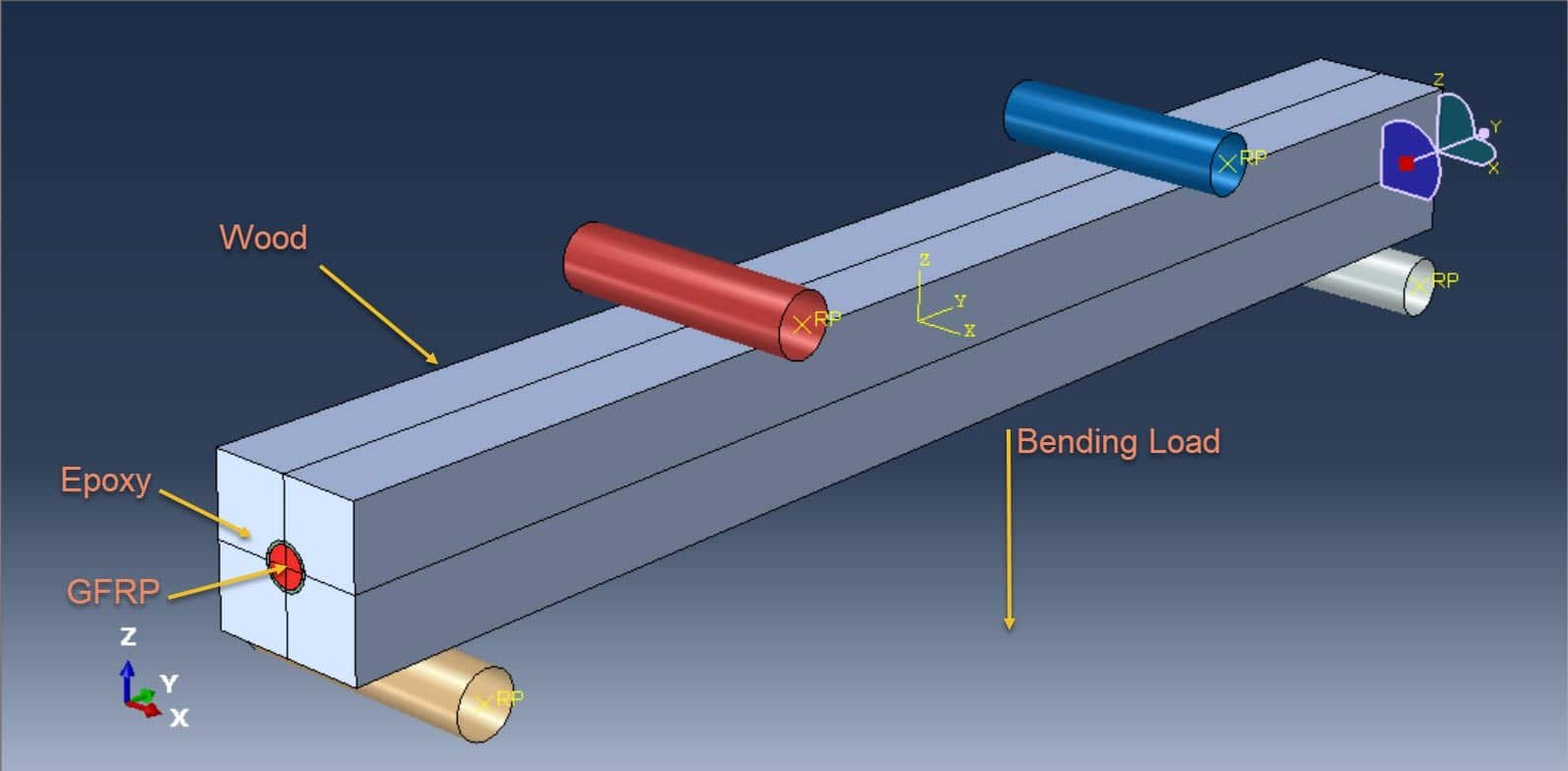
1. Specimen Preparation:
Timber beams are cut to standardized dimensions.
Grooves are made along the length of the beam to embed GFRP rods.
The rods are bonded using an epoxy resin to ensure proper load transfer.
2. Test Setup:
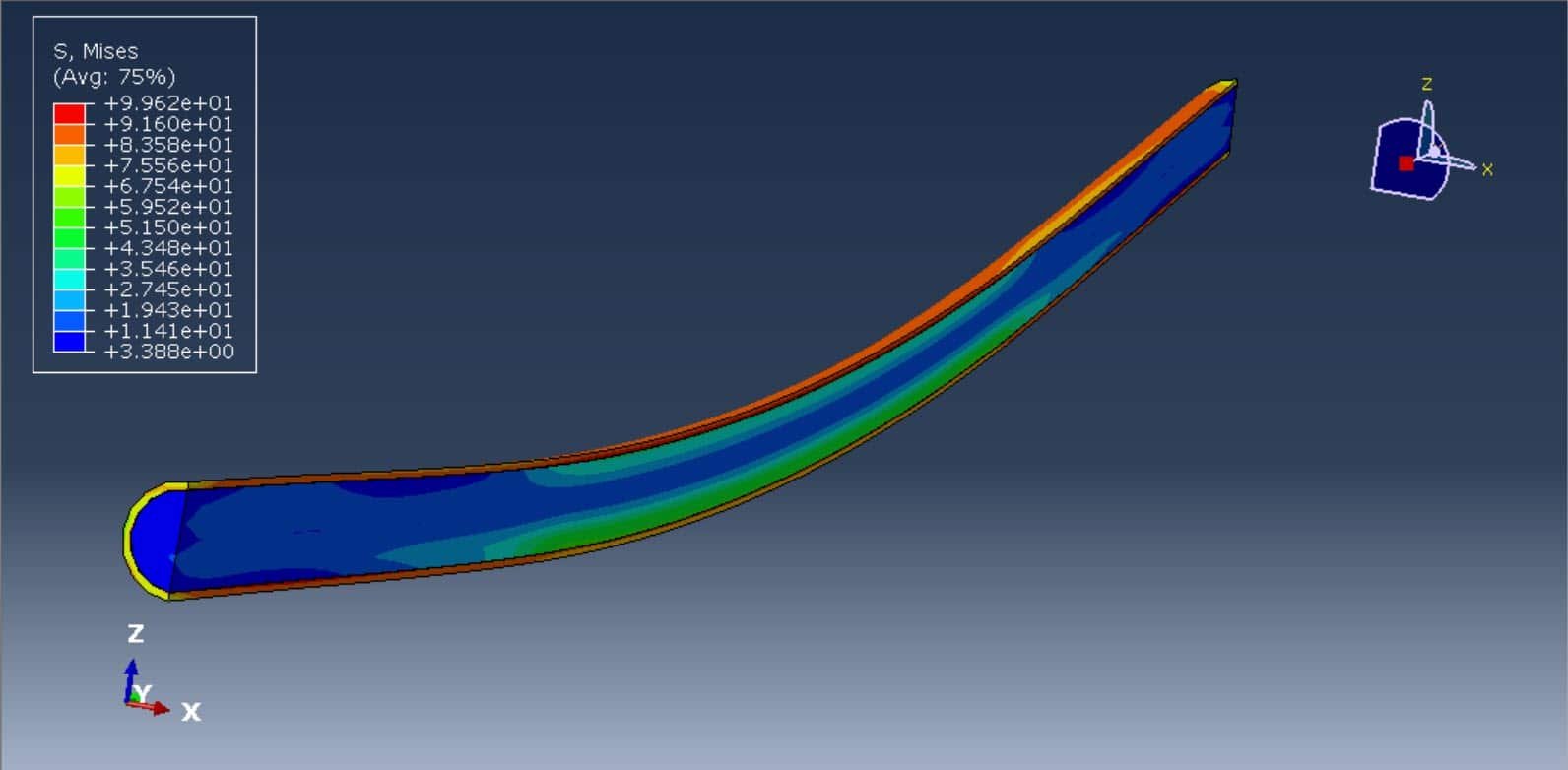
A three-point or four-point bending test is conducted under controlled conditions. Deflections, strains, and failure patterns are recorded using LVDTs, strain gauges, and digital imaging.
3. Parameters Studied:
Load-deflection behavior
Ultimate bending moment capacity
Stiffness enhancement due to GFRP reinforcement
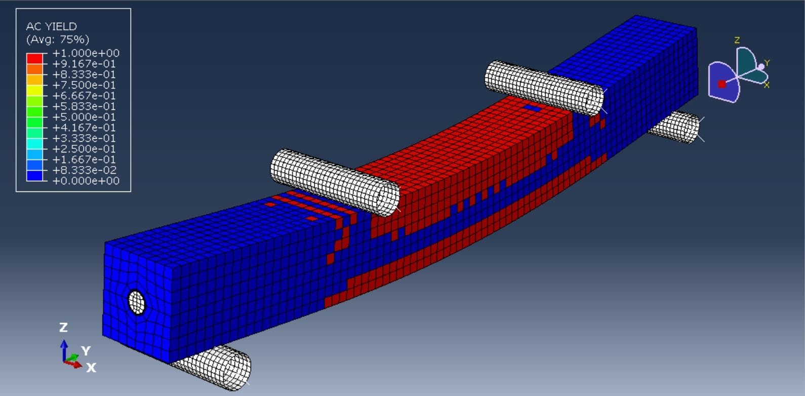
Failure mechanisms (e.g., timber crushing, GFRP debonding, or rod rupture)
Expected Outcomes
Increased load-carrying capacity and reduced deflection in reinforced beams.
Improved ductility due to the GFRP rod’s ability to resist tensile stresses.
Potential failure modes include **timber compression failure, adhesive bond failure, or GFRP rupture.
Significance
This research contributes to sustainable construction practices by enhancing the structural efficiency of timber beams, reducing material consumption, and extending service life. The findings can guide design codes for FRP-reinforced timber structures in civil engineering applications.
In this practical example, the four-point bending test is performed using the general static step. The tutorial explains everything to have a comprehensive view of modeling timber beams.


Abaqus
€97,00 €54,00

Engineering files
€60,00 €50,00

Abaqus
€146,00 €89,00

Abaqus
€85,00 €47,00

Abaqus
€78,00 €39,00
See more

Want to receive push notifications for all major on-site activities?


